Fabric-based strain gauge

a strain gauge and fabric-based technology, applied in the field of strain gauges, can solve the problems of reducing mobility, difficult to mount on a living body, such as the human body or the limbs of animals, and failure to perform monitoring

Active Publication Date: 2010-07-06
YANG CHANG MING
View PDF3 Cites 24 Cited by
  • Summary
  • Abstract
  • Description
  • Claims
  • Application Information

AI Technical Summary

Benefits of technology

[0011]Therefore, an aspect of the invention is to provide a strain gauge, and more particularly, the strain gauge of the invention is based on a fabric, and therefore, has excellent flexibility, it can be integrated with a variety of fabrics to be worn on any objects.

Problems solved by technology

Because the strain gauge as described above is usually mounted to the solid structure through adhesion, it is hard to be mounted on a living body, such as human body or limbs of animals, to measure the movement of the living body.
However, most of the physical function monitoring apparatus / systems as disclosed in the references above have to perform monitoring at a fixed location, thus reducing mobility, and it may fail to perform monitoring because of user's carelessness.
Additionally, some of the monitoring apparatus as described above can be worn on a user, so as to perform monitoring at anytime and anywhere; however, the weight and size of these apparatus may be a burden or may cause difficulty in the movements of the user.

Method used


Image

  • Fabric-based strain gauge
  • Fabric-based strain gauge
  • Fabric-based strain gauge

Examples


Embodiment Construction

[0026]As used herein, the term “fiber” refers to staple fiber (short fiber) or filament (long fiber).

[0027]According to a preferred embodiment of the invention, the strain gauge includes a fabric base and at least one conductive yarn.

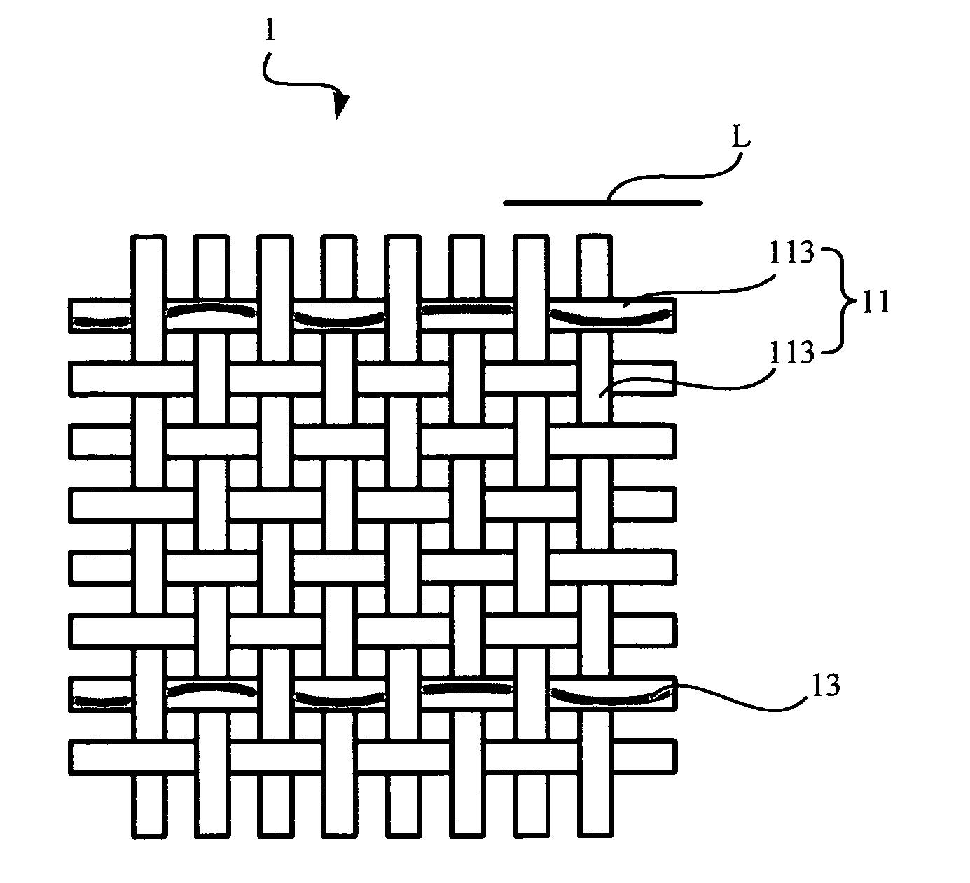
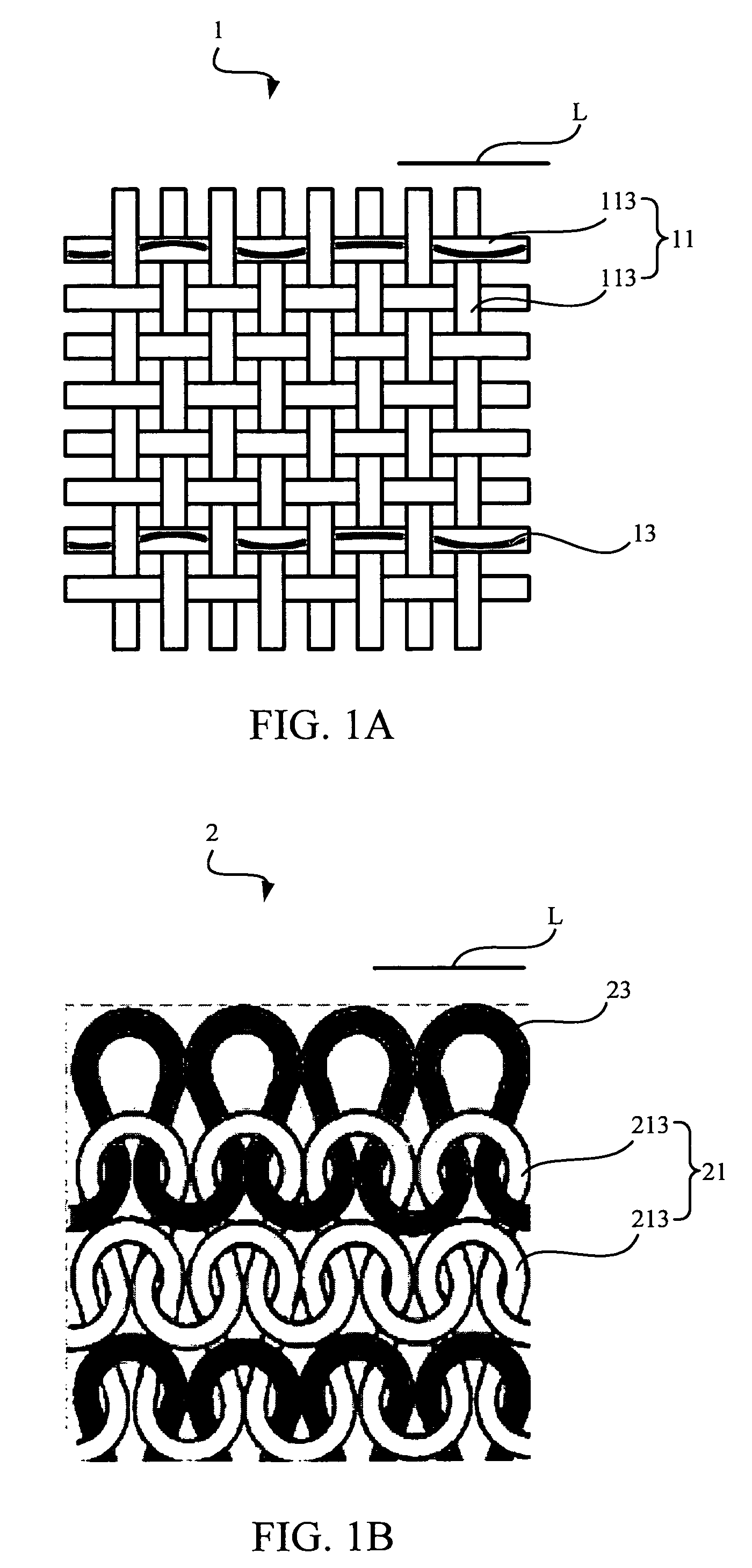
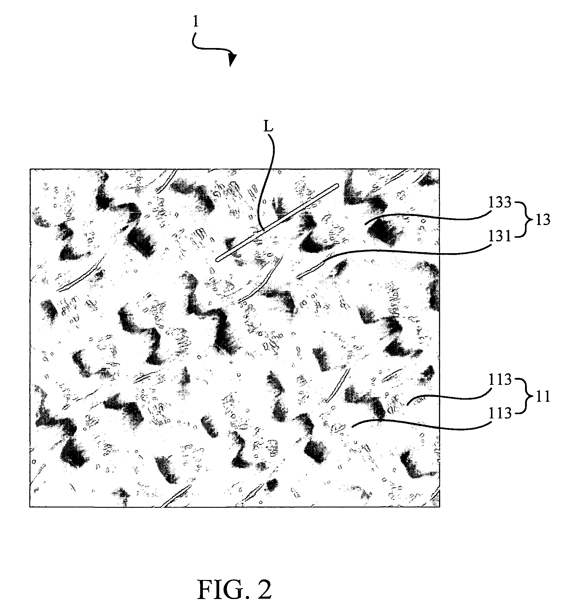
[0028]The fabric base is weaved with a plurality of non-conductive yarns, and the fabric base thereon defines a sensing direction. In an embodiment, the plurality of non-conductive yarns have elasticity, so that the strain gauge can fit to any kind of surface, such as chest, elbow, and knee, to enhance the sensitivity and accuracy of measurement. For example, the non-conductive yarns can be natural elastic yarns, or synthetic elastic yarns. However, in another embodiment, parts of the plurality of non-conductive yarns can optionally have different elasticity. In yet another embodiment, only one or several of the plurality of non-conductive yarns have elasticity.

[0029]Furthermore, each of the conductive yarn is gimped with one of the non-conductive yarns...


PUM

PropertyMeasurementUnit
diameteraaaaaaaaaa
diameteraaaaaaaaaa
constant resistanceaaaaaaaaaa

Abstract

The invention provides a strain gauge which includes a fabric base and at least one conductive yarn. In addition, the fabric base is weaved with a plurality of non-conductive yarns, and the fabric base thereon defines a sensing direction. Moreover, each of the conductive yarn is gimped by a textile process with one of the non-conductive yarns and is woven through the fabric base along the sensing direction. Furthermore, the at least one conductive yarn is capable of being applied by an electric power; when an external force acts on the fabric base, the geometrical property of the at least one conductive yarn alters so that a change of an electric property associated with the applied electric power is sensed to indicate an elongation of said strain gauge applied by the external force along the sensing direction.

Description

BACKGROUND OF THE INVENTION[0001]1. Field of the Invention[0002]The invention is related to a strain gauge and, more particularly, to a fabric-based strain gauge.[0003]2. Description of the Prior Art[0004]Strain gauge, or named strainometer, of the prior art used to be a metal wire formed by a resistor with a constant resistance, such as 120 ohm, 350 ohm, or 1000 ohm. Furthermore, based on the principle that the proportion of the change of the length of the metal wire and the change of resistance of the metal wire is directly proportional, when an external force, such as a pulling force, pressure, tension, and other forces, acts on the metal wire and causes change in the length of the metal wire, the change of its resistance and the change of its length are directly proportional. Therefore, we can calculate the strength of the external force by measuring the change of its resistance.[0005]Because of the simple principle and convenient usage, strain gauge has been widely applied in t...

Claims


Application Information

Patent Timeline
Patent Type & Authority Patents(United States)
IPC IPC(8): G01L1/22
CPCG01L1/22Y10T428/2913Y10T428/29A61B5/1135A61B5/6805Y10T442/102
Inventor YANG, CHANG MINGCHOU, CHUN-MEI
Owner YANG CHANG MING
Why Eureka
Try Eureka