High-resolution autostereoscopic display

a high-resolution, auto-stereoscopic technology, applied in optics, instruments, electrical equipment, etc., can solve the problems of directional backlight technology, more complicated manufacturing, and drawbacks of prior technology based on directional backlight technology

Inactive Publication Date: 2010-07-06
SAMSUNG ELECTRONICS CO LTD
View PDF19 Cites 87 Cited by
  • Summary
  • Abstract
  • Description
  • Claims
  • Application Information

AI Technical Summary

Problems solved by technology

The above-described prior technology is based on a directional backlight which is usually very thick and is more complicated to manufacture than a conventional diffuse backlight for an LCD.
However, the prior technology based on the directional backlight has drawbacks due to complicated manufacturing and large size.

Method used


Image

  • High-resolution autostereoscopic display
  • High-resolution autostereoscopic display
  • High-resolution autostereoscopic display

Examples


Embodiment Construction

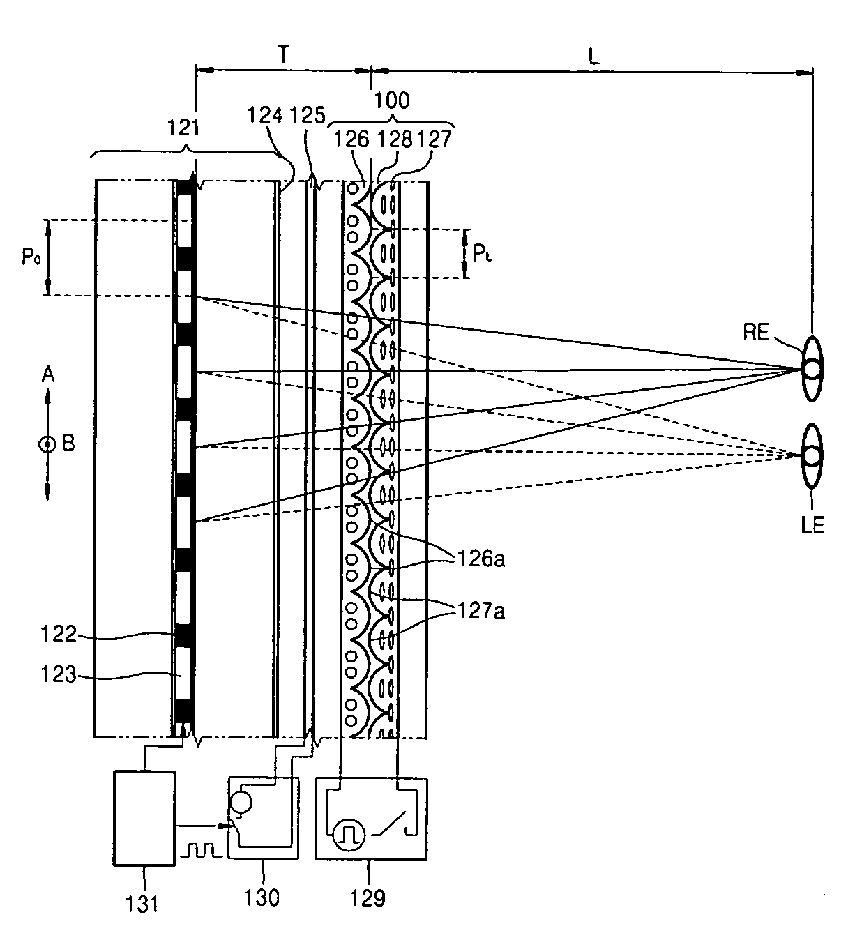
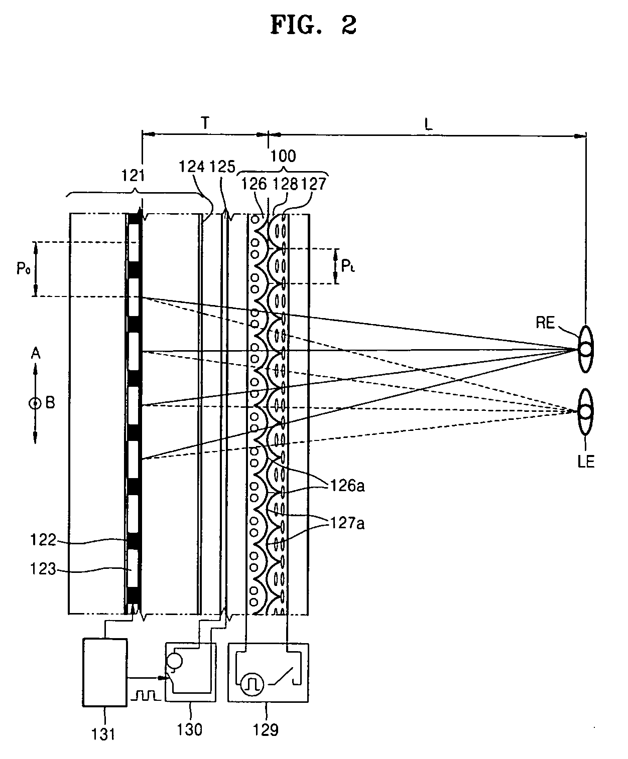
[0027]Referring to FIG. 2, an autostereoscopic display according to an exemplary embodiment of the present invention includes a display panel 121, a polarizer 124 polarizing light emitted from the display panel 121 in one direction, a polarization switch 125 switching the polarization of the polarized light, and an electro-optical birefringent unit 100 with varying refraction characteristics according to the polarization of incident light.

[0028]The display panel 121 electrically modulates light to form an image and may be implemented as a plasma display panel (PDP), organic light emitting display (OLED) panel, field emission display panel (FED) which requires the polarizer 124 to be installed as well as a liquid crystal display (LCD) or a ferro-electric LCD (FELCD), which conventional structure already includes the polarizer 124 as output polarizer. The display panel 121 includes pixels 122 arranged in rows and columns and an inactive area 123 disposed between the pixels 122. The in...


PUM

PropertyMeasurementUnit
electro-optical birefringentaaaaaaaaaa
birefringentaaaaaaaaaa
refractive indexaaaaaaaaaa

Abstract

A high-resolution autostereoscopic display is provided. The autostereoscopic display includes a controller; a display panel receiving an image signal from the controller, forming an image, and including pixels and an inactive area between the pixels; a polarizer polarizing light emitted from the display panel to have a first polarization; a polarization switching controller; a polarization switch selectively converting the light with the first polarization into light with a second polarization in response to the electrical control of the polarization switching controller; a selection controller; a first electro-optical birefringent layer having an optical axis that direction is changed by an electrical control of the selection controller and including a plurality of first lenticular lenses separated by a predetermined pitch; and a second electro-optical birefringent layer having an optical axis that direction is changed by the electrical control of the selection controller, includes a plurality of second lenticular lenses that are arranged with the same pitch as the first lenticular lenses are and shifted by half the pitch from the first lenticular lenses.

Description

CROSS-REFERENCE TO RELATED PATENT APPLICATIONS[0001]This application claims the benefit of Korean Patent Application No. 10-2005-0071484, filed on Aug. 4, 2005, in the Korean Intellectual Property Office, the disclosure of which is incorporated herein in its entirety by reference.BACKGROUND OF THE INVENTION[0002]1. Field of the Invention[0003]The present invention relates to an autostereoscopic display, and more particularly, to an autostereoscopic display which allows conversion between a two-dimensional (2D) mode and a three-dimensional (3D) mode without a decrease in resolution and is manufactured as a flat panel for television, computer graphics, and other applications.[0004]2. Description of the Related Art[0005]An effective method of providing a stereoscopic image through a flat panel display is a lenticular method using a lenticular lens array located between an image panel and a viewer to separate a viewing zone of a left eye image from a viewing zone of a right eye image in...

Claims


Application Information

Patent Timeline
Patent Type & Authority Patents(United States)
IPC IPC(8): G02F1/1335G02B30/25G02B30/28
CPCG02B27/2214H04N13/0404H04N13/0454H04N13/305H04N13/359G02B30/28G02B30/27
Inventor SHESTAK, SERGEYKIM, DAE-SIKKIM, TAE-HEE
Owner SAMSUNG ELECTRONICS CO LTD
Why Eureka
Try Eureka