Leaky-bucket thread scheduler in a multithreading microprocessor

a multi-threading microprocessor and thread scheduler technology, applied in the field of instruction issue scheduling, can solve the problems of limited performance improvement that may be achieved through exploitation of instruction-level parallelism, inability to perform cache misses, and inability to perform all pipeline stages of a single-threaded microprocessor idle performing no useful work for many clock cycles

Active Publication Date: 2010-07-06
ARM FINANCE OVERSEAS LTD
View PDF101 Cites 36 Cited by
  • Summary
  • Abstract
  • Description
  • Claims
  • Application Information

AI Technical Summary

Benefits of technology

[0017]An advantage of the present invention is that by including a parameterized feedback mechanism regarding executed instructions, thread management software is enabled to respond to the feedback and enforce a required quality of service in terms of instruction execution rate and resolution as necessitated by the application.
is that by including a parameterized feedback mechanism regarding executed instructions, thread management software is enabled to respond to the feedback and enforce a required quality of service in terms of instruction execution rate and resolution as necessitated by the application.

Problems solved by technology

However, the performance improvement that may be achieved through exploitation of instruction-level parallelism is limited.
One example of a performance-constraining issue addressed by multithreading microprocessors is the fact that accesses to memory outside the microprocessor that must be performed due to a cache miss typically have a relatively long latency.
Consequently, some or all of the pipeline stages of a single-threaded microprocessor may be idle performing no useful work for many clock cycles.
Another problem, particularly in embedded systems, is the wasted overhead associated with interrupt servicing.

Method used


Image

  • Leaky-bucket thread scheduler in a multithreading microprocessor
  • Leaky-bucket thread scheduler in a multithreading microprocessor
  • Leaky-bucket thread scheduler in a multithreading microprocessor

Examples


Embodiment Construction

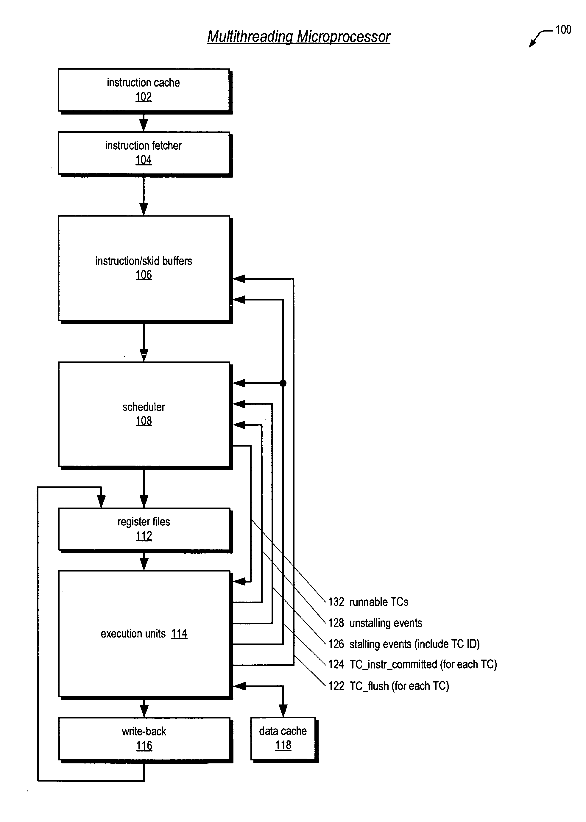
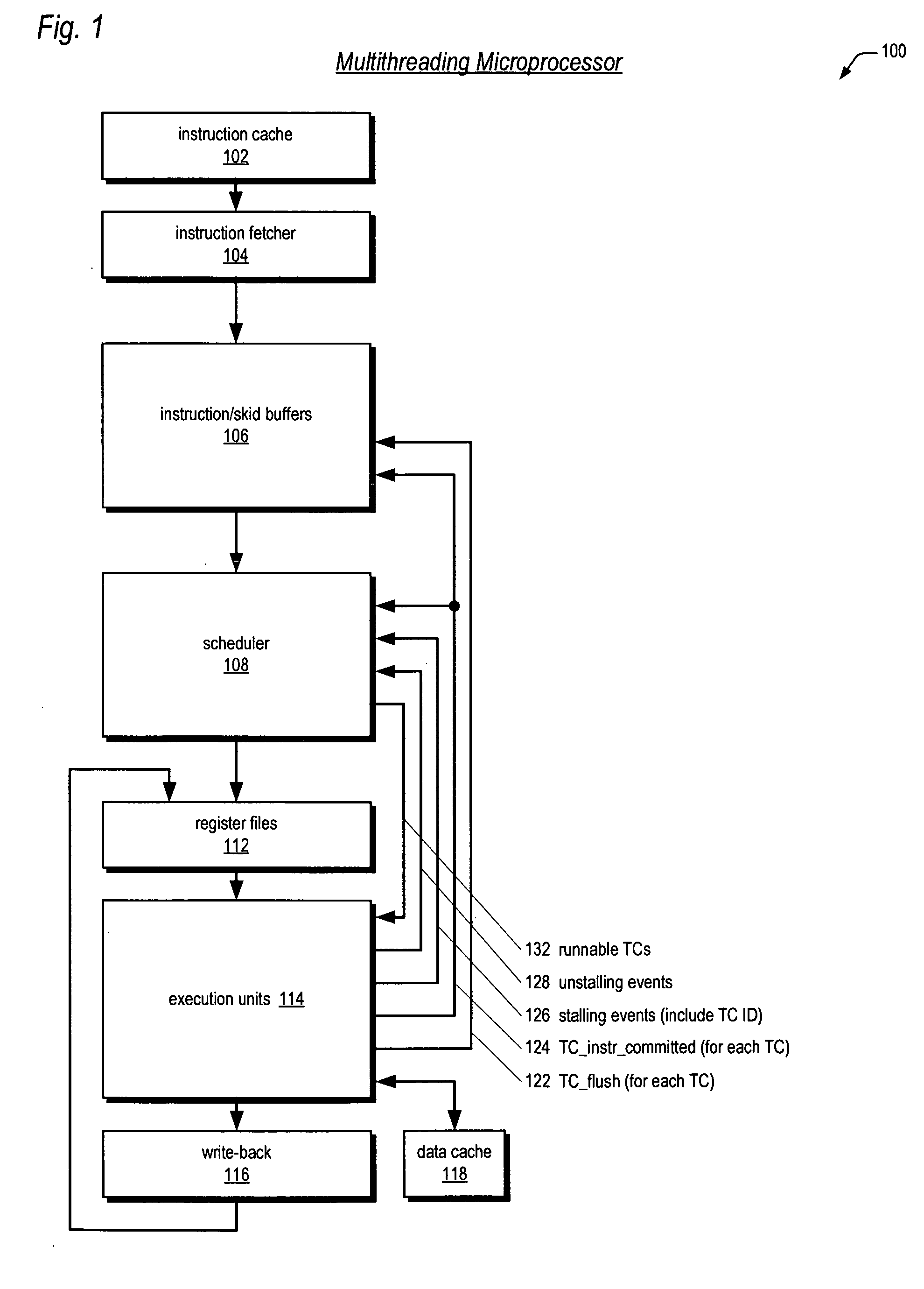
[0033]Referring now to FIG. 1, a block diagram illustrating a pipelined multithreading microprocessor 100 according to the present invention is shown. The microprocessor 100 is configured to concurrently execute a plurality of threads. A thread—also referred to herein as a thread of execution, or instruction stream—comprises a sequence, or stream, of program instructions. The threads may be from different programs executing on the microprocessor 100, or may be instruction streams from different parts of the same program executing on the microprocessor 100, or a combination thereof.

[0034]Each thread has an associated thread context (TC). A thread context comprises a collection of storage elements, such as registers or latches, and / or bits in the storage elements of the microprocessor 100 that describe the state of execution of a thread. That is, the thread context describes the state of its respective thread, which is unique to the thread, rather than state shared with other threads ...


PUM


Abstract

A leaky-bucket style thread scheduler for scheduling concurrent execution of multiple threads in a microprocessor is provided. The execution pipeline notifies the scheduler when it has completed instructions. The scheduler maintains a virtual water level for each thread and decreases it each time the execution pipeline executes an instruction of the thread. The scheduler includes an instruction execution rate for each thread. The scheduler increases the virtual water level based on the requested rate per a predetermined number of clock cycles. The scheduler includes virtual water pressure parameters that define a set of virtual water pressure ranges over the height of the virtual water bucket. When a thread's virtual water level moves from one virtual water pressure range to the next higher range, the scheduler increases the instruction issue priority for the thread; conversely, when the level moves down, the scheduler decreases the instruction issue priority for the thread.

Description

CROSS REFERENCE TO RELATED APPLICATION(S)[0001]This application is related to and filed concurrently with the following Non-Provisional U.S. patent applications, each of which is incorporated by reference in its entirety for all purposes:[0002]Ser. No.Filing DateTitle11 / 051,997, issued asFeb. 4, 2005BIFURCATED THREADU.S. Pat. No. 7,613,904SCHEDULER IN AMULTITHREADINGMICROPROCESSOR11 / 051,979, issued asFeb. 4, 2005MULTITHREADINGU.S. Pat. No. 7,657,891MICROPROCESSOR WITHOPTIMIZED THREADSCHEDULER FORINCREASING PIPELINEUTILIZATION EFFICIENCY11 / 051,998, issued asFeb. 4, 2005MULTITHREADINGU.S. Pat. No. 7,664,936PROCESSOR INCLUDINGTHREAD SCHEDULERBASED ON INSTRUCTIONSTALL LIKELIHOODPREDICTION11 / 051,978Feb. 4, 2005INSTRUCTION / SKIDBUFFERS IN AMULTITHREADINGMICROPROCESSORFIELD OF THE INVENTION[0003]The present invention relates in general to the field of multithreaded processors, and particularly to instruction issue scheduling among multiple threads of execution.BACKGROUND OF THE INVENTION[00...

Claims


Application Information

Patent Timeline
Patent Type & Authority Patents(United States)
IPC IPC(8): G06F9/46G06F9/30
CPCG06F9/3814G06F9/3851G06F9/3861G06F9/4881Y02D10/00
Inventor JONES, DARREN M.KINTER, RYAN C.PETERSEN, THOMAS A.VISHIN, SANJAY
Owner ARM FINANCE OVERSEAS LTD
Why Eureka
Try Eureka