[0008]Accordingly, it is a principal advantage of the present invention to overcome some or all of these limitations and to provide a hold-down assembly that is self-adjusting to provide substantially continuous resistance to upward movement of building elements.
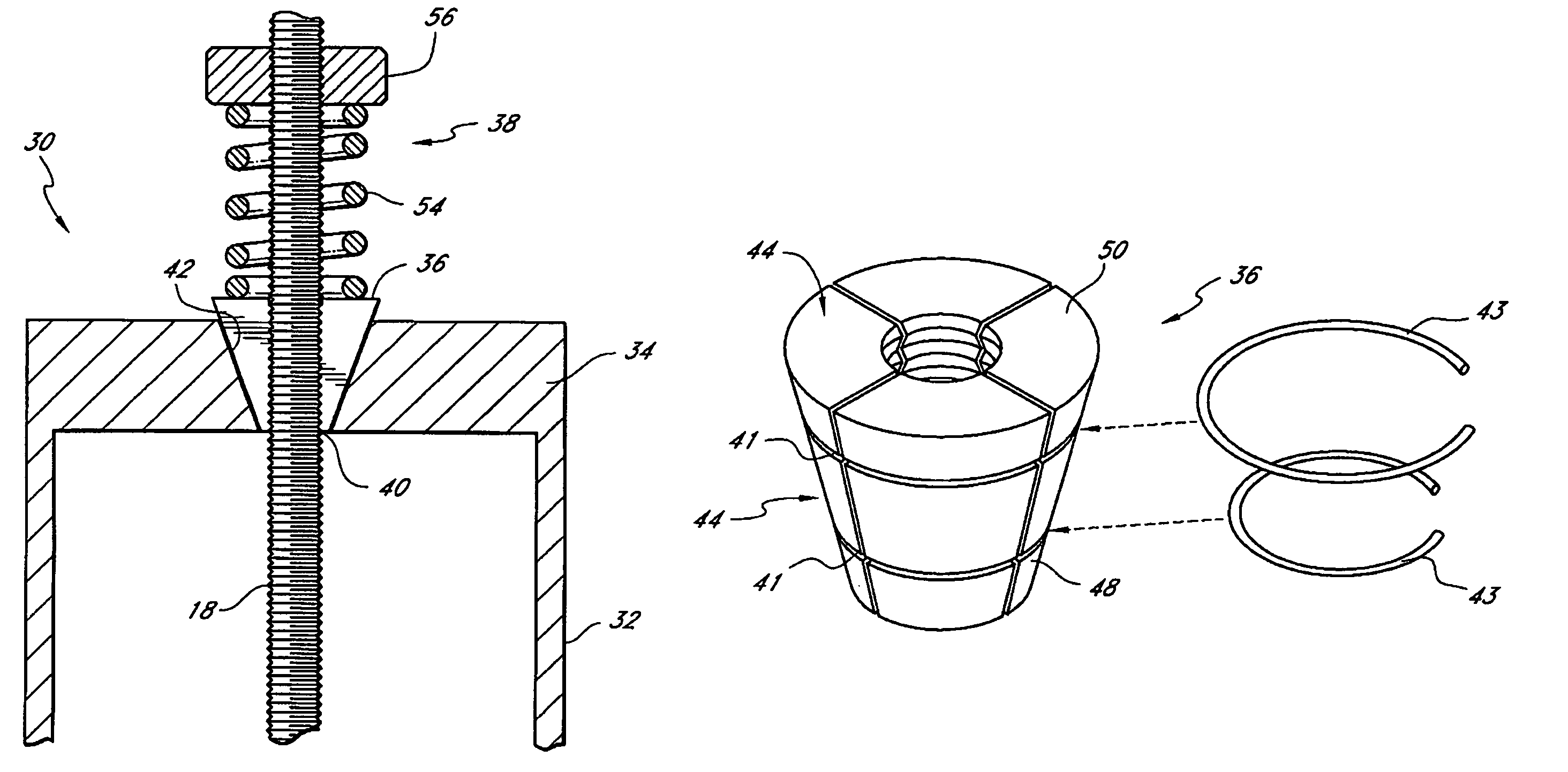
[0009]In one aspect, the present invention provides a hold-down assembly comprising a generally vertical stud, a generally vertical rod, a stud-connector, a rod-gripper, and a gripper-positioning element. The stud forms part of a building structure. The rod has a lower end secured to a stable building element (e.g., building foundation) configured to have a substantially constant vertical position during downward settling of elements of the building structure. The stud-connector is secured with respect to the stud at a position displaced from a lower end of the stud. The stud-connector has an opening within which the rod is received, the opening defining a frustoconical bearing surface on an upper surface of a portion of the stud-connector. The rod-gripper comprises a plurality of separate gripping portions generally surrounding the rod above the frustoconical bearing surface of the stud-connector. Each of the gripping portions has a rod-engagement surface and a lower surface. Each of the rod-engagement surfaces has teeth configured to engage circumferential teeth of a circumferential portion of the rod. Each of the lower surfaces of the gripping portions is sized and adapted to bear against a circumferential portion of the frustoconical bearing surface of the stud-connector.
[0010]The gripper-positioning element exerts a downward force onto the rod-gripper. Downward movement of the stud and stud-connector with respect to the rod causes the downward force exerted by the gripper-positioning element onto the rod-gripper to result in disengagement of the teeth of the gripping portions from the teeth of the rod so that the rod-gripper moves downward until the lower surfaces of one or more of the gripping portions bears against the frustoconical bearing surface of the stud-connector. The bearing of the lower surfaces of the one or more gripping portions against the frustoconical bearing surface of the stud-connector causes the teeth of the gripping portions to reengage the teeth of the rod.
[0011]In another aspect, the present invention provides a hold-down kit for a building, comprising a rod, a stud-connector, and a rod-gripper. The rod has a lower end configured to be secured to a stable building element that has a substantially constant vertical position during downward settling of elements of the building. The stud-connector is configured to be secured with respect to a generally vertical stud at a position displaced from a lower end of the stud. The stud-connector has an opening configured to receive the rod. The opening defines a frustoconical bearing surface on an upper surface of a portion of the plate. The rod-gripper comprises a plurality of gripping portions each having a rod-engagement surface and a lower surface. Each of the rod-engagement surfaces has teeth configured to engage circumferential teeth of a circumferential portion of the rod. Each of the lower surfaces of the gripping portions is sized and adapted to bear against a circumferential portion of the frustoconical bearing surface of the stud-connector. The gripping portions are adapted to generally surround the rod with the teeth of the rod-engagement surfaces engaging the teeth of the rod so that the gripping portions, when radially compressed together, are substantially prevented from moving vertically with respect to the rod.
[0012]In still another aspect, the present invention provides a hold-down kit comprising a nut-supporting element and a segmented nut. The nut-supporting element is adapted to be secured to a stud-connector that is secured with respect to a generally vertical stud at a position displaced from a lower end of the stud. The nut-supporting element has an opening configured to receive a generally vertical threaded rod. The opening defines a frustoconical bearing surface on an upper surface of the nut-supporting element. The segmented nut comprises a plurality of nut portions each having a rod-engagement surface and a lower surface. Each of the rod-engagement surfaces has threads configured to engage threads of a circumferential portion of the rod. Each of the lower surfaces of the nut portions is sized and adapted to bear against a circumferential portion of the frustoconical bearing surface of the nut-supporting element. The nut portions are adapted to generally surround the rod with the threads of the rod-engagement surfaces engaging the threads of the rod so that the nut portions, when radially compressed together, are substantially prevented from moving vertically with respect to the rod.
[0013]In yet another aspect, the present invention provides a method of holding down a building construction. A generally vertical rod is provided generally parallel to a generally vertical stud of a building structure. A lower portion of the rod is secured to a stable building element configured to have a substantially constant vertical position during downward settling of elements of the building structure. A stud-connector is provided, having an opening configured to receive the rod. The stud-connector is engaged with the rod so that the rod is received within the opening of the stud-connector. The stud-connector is secured with respect to the stud. A rod-gripping member is engaged onto the rod closely above the opening of the stud-connector. The rod-gripping member comprises a plurality of gripping portions generally surrounding the rod. Each of the gripping portions has a rod-engagement surface with teeth configured to engage circumferential teeth of a circumferential portion of the rod. The gripping portions are sized so that when they are compressed radially inward into toothed engagement with the rod the rod-gripping member and rod have a horizontal cross section that is too large to pass downward through the opening of the stud-connector. Finally, the method includes reacting to a downward movement of the stud and stud-connector with respect to the rod and rod-gripping member by pushing the rod-gripping member downward with respect to the rod until the rod-gripping member is in toothed engagement with the rod closely above the opening of the stud-connector.

