Leg type mobile robot
a mobile robot and leg-type technology, applied in the field of leg-type mobile robots, can solve the problems of reducing the longevity of the elastic member, reducing the locomotion speed of the leg-type member, and exhibiting a relatively small stroke of compression, so as to increase the locomotion speed, increase the resistance force, and move easily
- Summary
- Abstract
- Description
- Claims
- Application Information
AI Technical Summary
Benefits of technology
Problems solved by technology
Method used
Image
Examples
first embodiment
[Bipedal Mobile Robot]
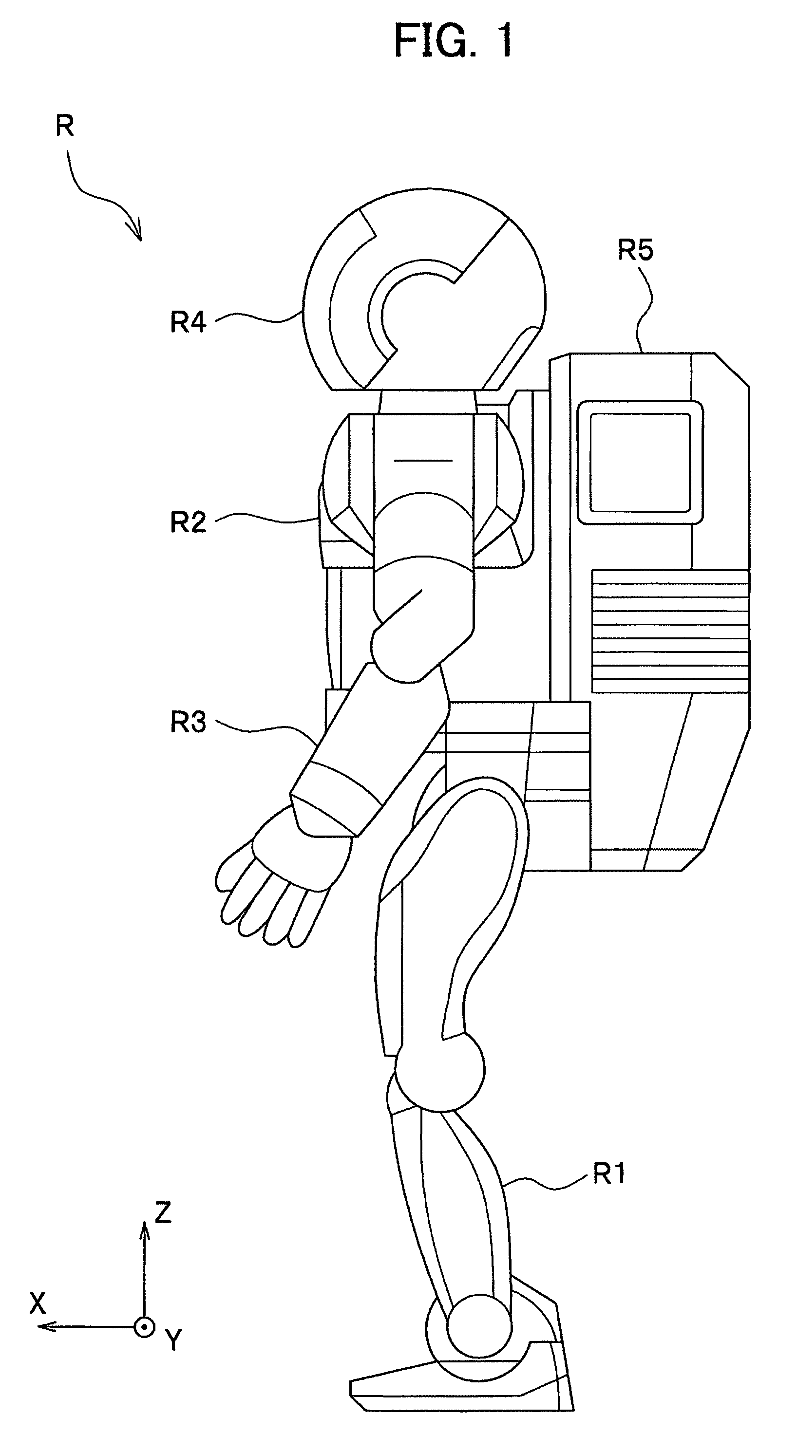
[0048]Referring now to FIG. 1, a bipedal mobile robot according to a first embodiment of the present invention will be described. The front-back direction, right-left direction and vertical direction of the bipedal mobile robot are represented by X-axis (the front side of robot R is designated as front or normal direction), Y-axis (the left side of the robot R is designated as normal direction) and Z-axis (the upper side of robot R is designated as normal direction), respectively. Expressions for the position and direction or the like of the bipedal mobile robot are described on the basis of a state where the bipedal mobile robot takes an upright standing posture.
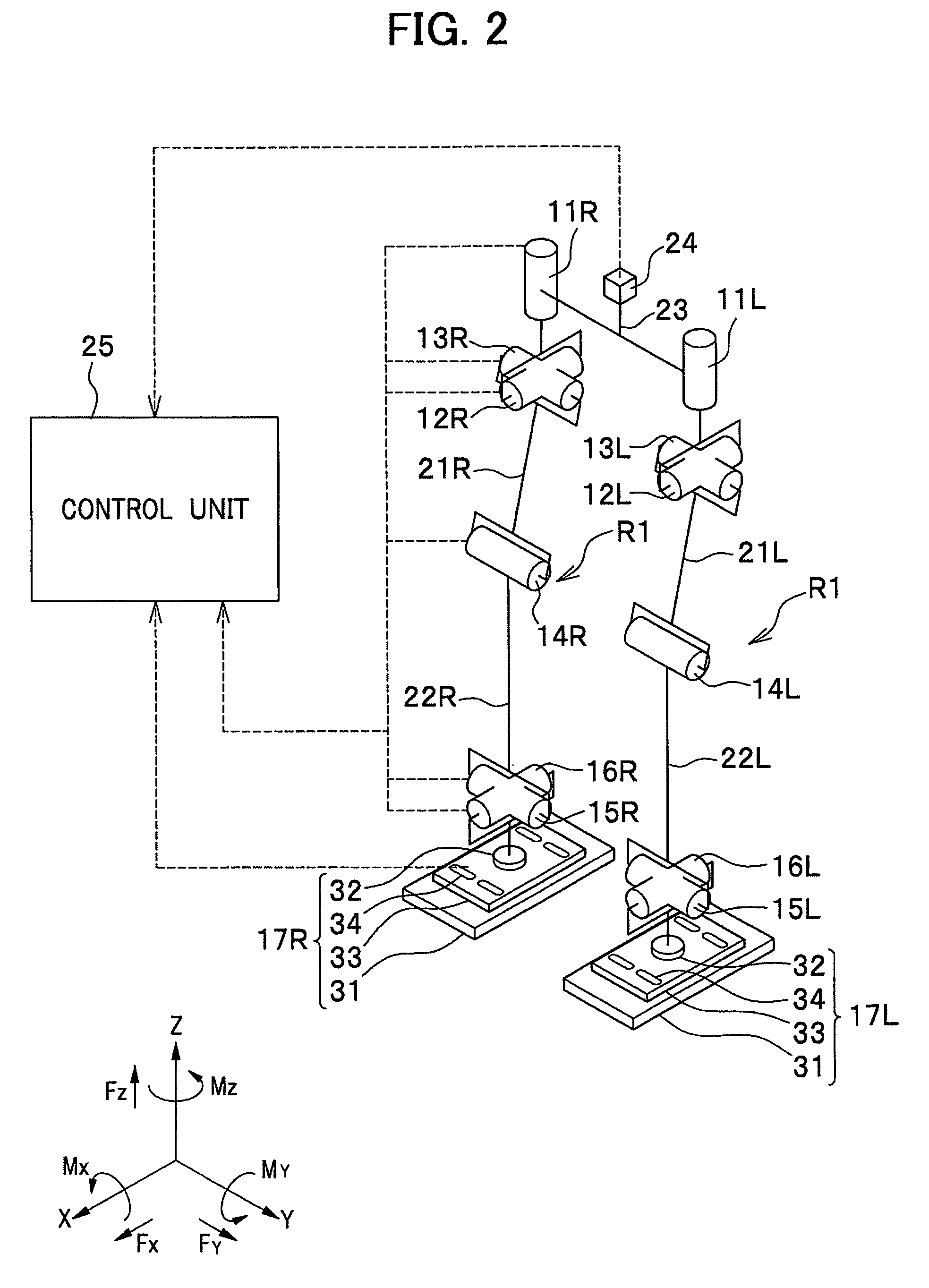
[0049]As shown in FIG. 1, a bipedal mobile robot (hereinafter referred to simply as ‘robot’) R stands and autonomously moves (walks, runs, or otherwise) using two legs R1 (only one leg is shown) in the same manner as a human. The bipedal mobile robot R in the present embodiment includes a body R2, two ...
second embodiment
[0092]A bipedal mobile robot according to a second embodiment is similar to the first embodiment which has been described with reference to FIGS. 1 through 4, except that a four-bar linkage is used in the shock absorbing assembly 34 of the foot 17. Therefore, the same elements will be designated by the same reference characters, and a duplicate description thereof will be omitted. An alternative shock absorbing assembly in the foot will hereafter be described with reference made to FIG. 13 (to FIGS. 3 and 4 where appropriate).
[0093]FIG. 13 schematically shows a foot of a bipedal mobile robot according to the second embodiment. The bipedal mobile robot according to the second embodiment, as in the first embodiment, includes four shock absorbing assemblies (though not all are shown) over the foot flat portion 131 of the foot 17. FIG. 13 shows a left-side half of the foot 17 (17R) of the robot R standing upright, as viewed from the normal direction of X-axis (i.e., right foot is viewed...
third embodiment
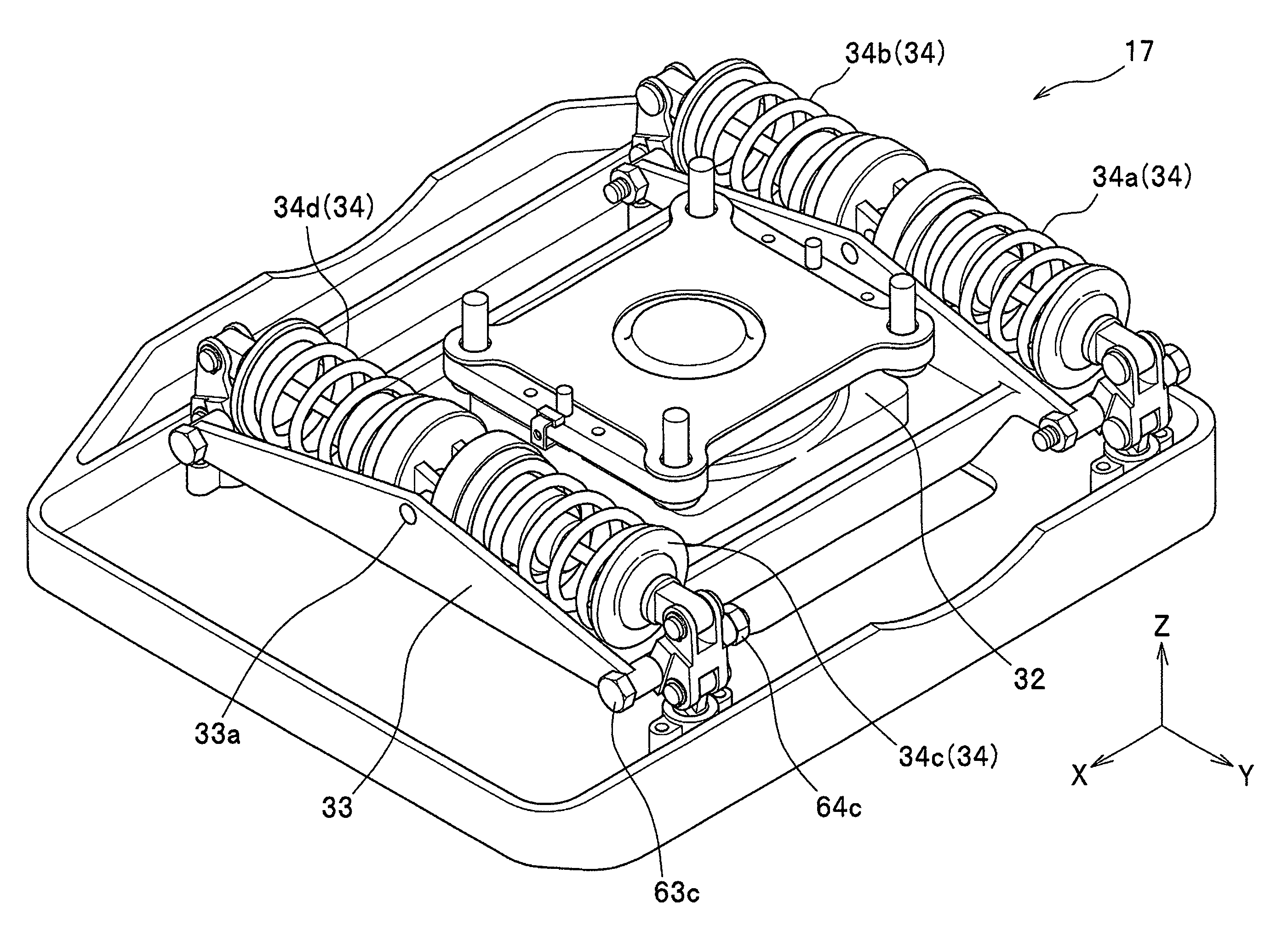
[0101]A bipedal mobile robot according to a third embodiment is similar to the first embodiment except that, in the foot 17 shown in FIG. 3, shock absorbing ability of the two shock absorbing assemblies 34c, 34d is different from shock absorbing ability of the two shock absorbing assemblies 34a, 34b, which are disposed in parallel across the force sensor 32 in a front-back direction thereof (in the X-axis direction). Therefore, the same elements will be designated by the same reference characters, and a duplicate description thereof will be omitted. The front-back direction (the X-axis direction) of the force sensor 32 is identical to the front-back direction of the foot flat portion 31 across the ankle joints (second joints) 15, 16. Shock absorbing ability of the shock absorbing assembly 34 varies according to a characteristic of the shock absorber 51 (see FIG. 5). In this embodiment, a characteristic of the shock absorber 51 is represented by repulsive force of the shock absorber ...
PUM
 Abstract
Description
Claims
Application Information
 - R&D
- Intellectual Property
- Life Sciences
- Materials
- Tech Scout
- Unparalleled Data Quality
- Higher Quality Content
- 60% Fewer Hallucinations
Browse by: Latest US Patents, China's latest patents, Technical Efficacy Thesaurus, Application Domain, Technology Topic, Popular Technical Reports.
© 2025 PatSnap. All rights reserved.Legal|Privacy policy|Modern Slavery Act Transparency Statement|Sitemap|About US| Contact US: help@patsnap.com


