
Optical module for an elliptical lighting device adapted to a given volume for a motor vehicle

a technology of elliptical lighting and optical modules, which is applied in the direction of vehicle interior lighting, transportation and packaging, lighting and heating apparatus, etc., can solve the problems of large general size of conventional elliptical lighting devices of the prior art in the direction of their length, and the inability to adapt to locations, and achieve the effect of satisfying the light rang

Inactive Publication Date: 2010-07-13
VALEO VISION SA
View PDF8 Cites 1 Cited by
  • Summary
  • Abstract
  • Description
  • Claims
  • Application Information

AI Technical Summary

Benefits of technology

The present invention is an optical module for an elliptical lighting device for motor vehicles. The module is designed to be integrated into the lighting device and can be adapted to the specific needs of the vehicle. The module has a reflector with a reflective surface that can be formed by merging the focuses of two ellipsoidal portions. The light source is placed close to the reflector and the light beam produced is directed towards the projection lens. The invention offers an optical solution for vehicles that allows for the reproduction of a non-conventional form of elliptical lighting device. The invention can be used in low beam type lighting devices for motor vehicles.

Problems solved by technology

Thus the general size of conventional elliptical lighting devices of the prior art is great in the direction of their length.
Such a spatial size thus does not make it possible to adapt to locations where the available space is reduced in depth; however, such considerations, in particular because of changes in the requirements of manufacturers, in particular in terms of style, are more and more frequent.
A problem is therefore posed for the design of certain lighting devices, the volumes that are reserved for them now having less conventional shapes than previously.

Method used


Image

  • Optical module for an elliptical lighting device adapted to a given volume for a motor vehicle
  • Optical module for an elliptical lighting device adapted to a given volume for a motor vehicle
  • Optical module for an elliptical lighting device adapted to a given volume for a motor vehicle

Examples


Embodiment Construction

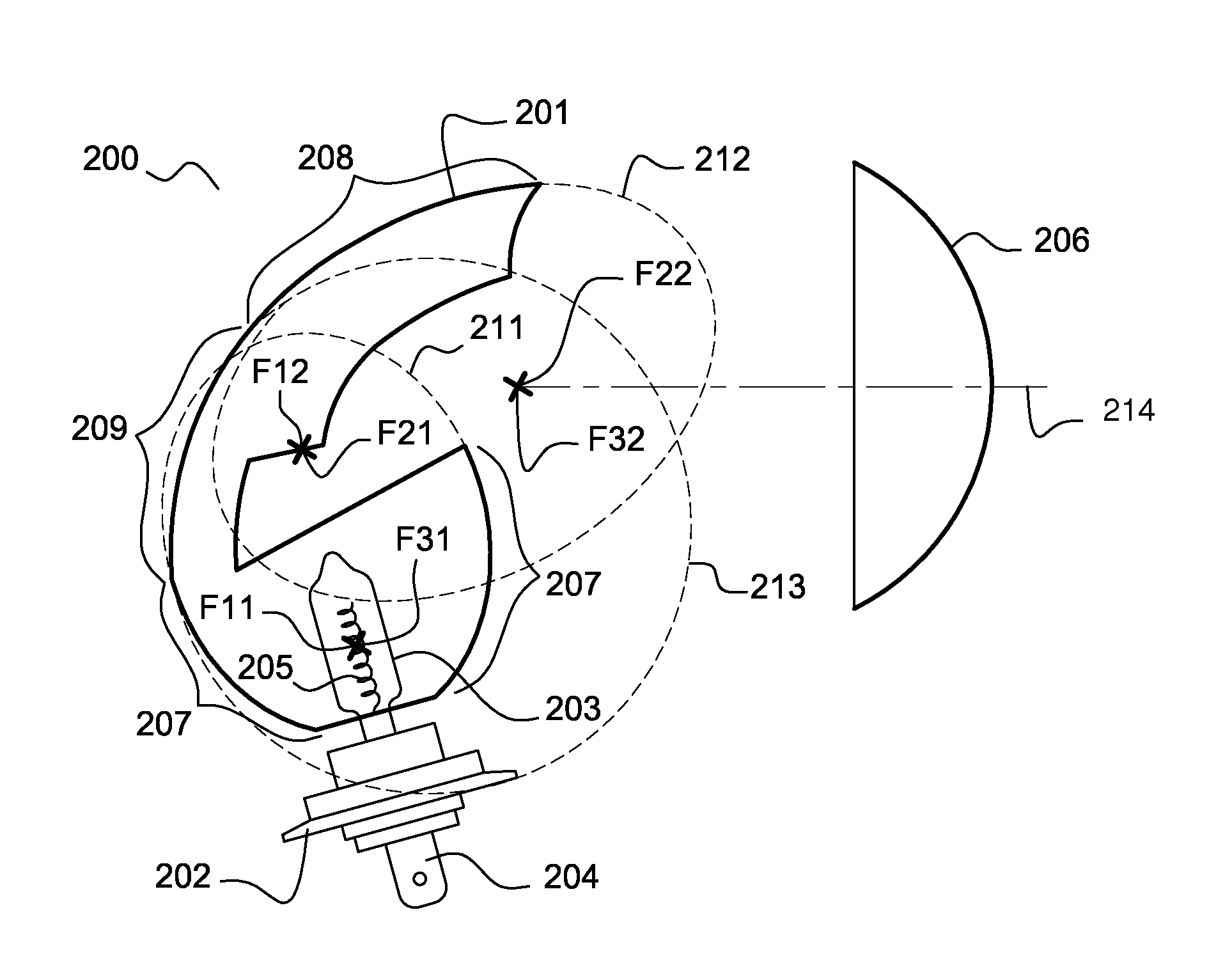
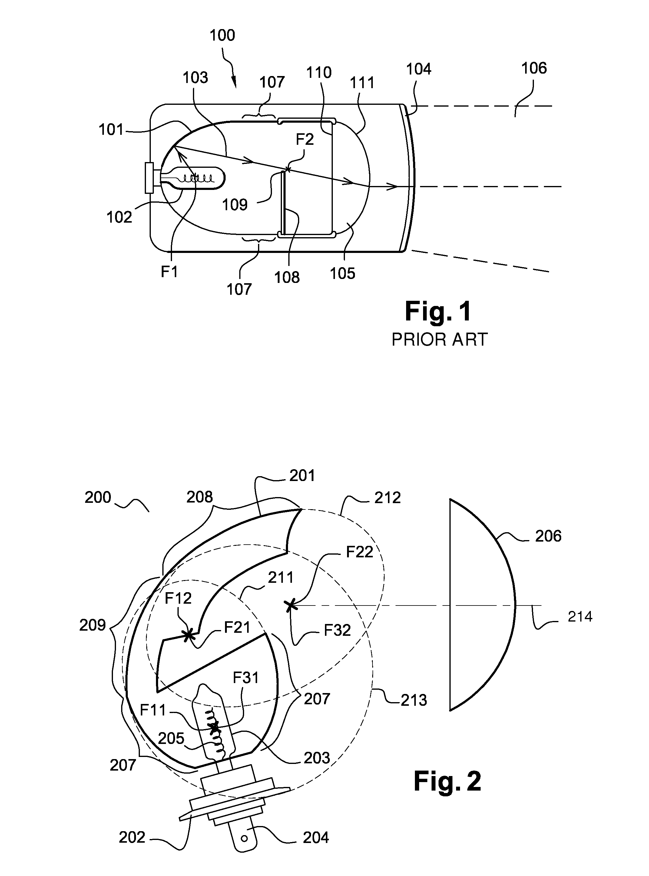
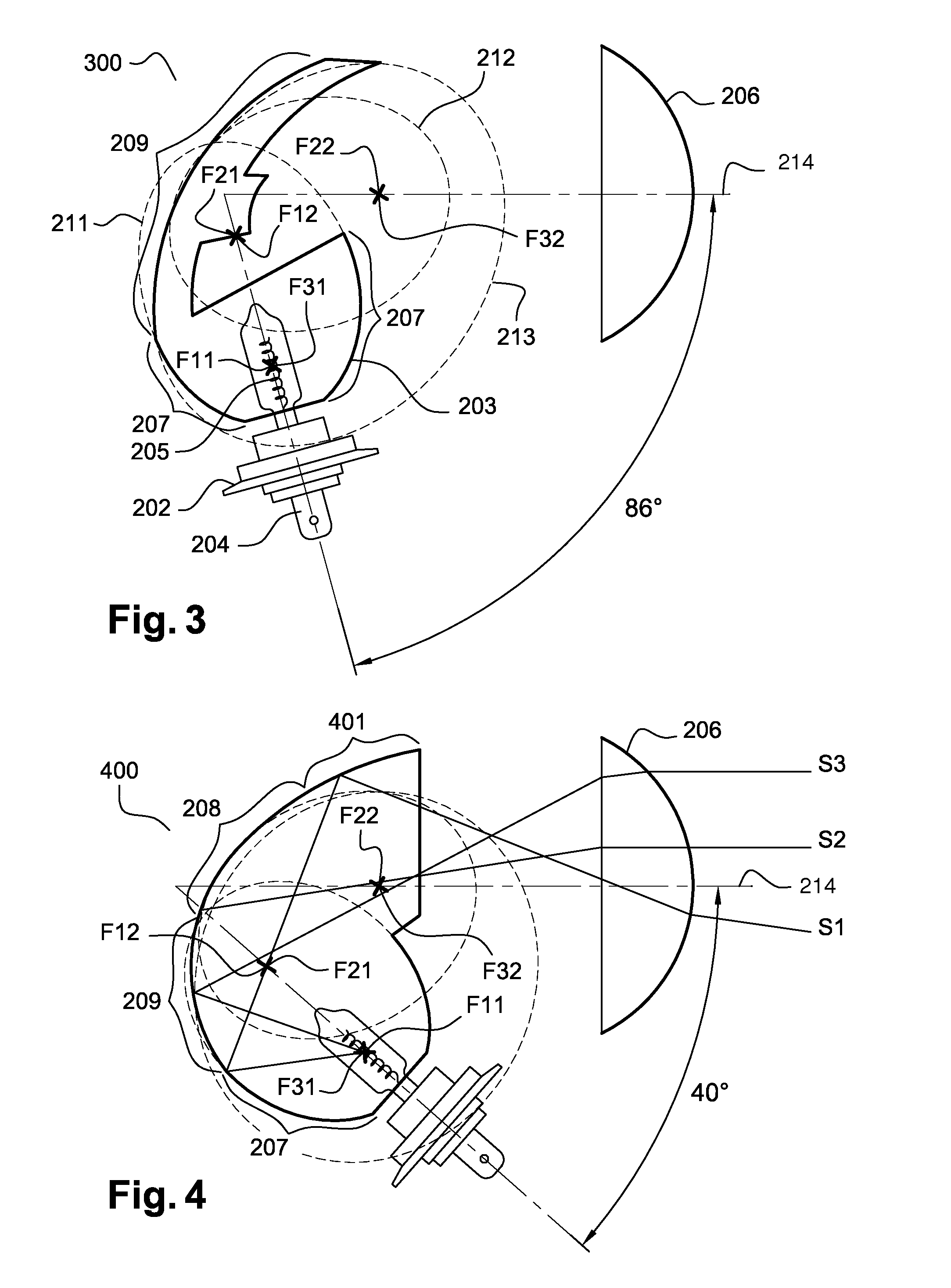
[0047]The various elements appearing in several figures will, unless otherwise specified, have kept the same reference. The concepts of direction and position of the “top”, “bottom”, “vertical”, “horizontal” etc type are mentioned under conventional conditions of use of the optical module according to the invention once it is disposed in a lighting device mounted on a motor vehicle.

[0048]FIG. 2 shows a first example of an optical module 200 according to the invention. It comprises a projection lens 206, and a reflector 201, within which there is positioned a light source 202, consisting essentially of a lamp 203, a lamp support 204 and a filament 205. In the examples considered, the lamps shown comprise filaments. The object of the invention obviously extends to optical modules involving other types of light source, in particular light emitting diodes, or LEDs, or xenon lamps; in the latter case, the filament 205 is replaced by an electric arc generating light rays.

[0049]The project...


PUM


Abstract

An optical module for an elliptical motor vehicle lighting device, the optical module comprising in particular a reflector, a light source emitting light rays, and a projection lens, the reflector having a reflecting internal face for reflecting towards the projection lens at least some of the light rays emitted by the light source. The internal face of the reflector is formed by the joining of at least a first portion of a first ellipsoid shape and a second portion of a second ellipsoid shape, the first ellipsoid shape having a first principal focus and a second principal focus, the second ellipsoid shape having a first principal focus and a second principal focus, the second principal focus of the first ellipsoid shape being merged with the first principal focus of the second ellipsoid shape.

Description

BACKGROUND OF THE INVENTION[0001]1. Field of the Invention[0002]The field of the invention is, in general terms, that of motor vehicle headlamps.[0003]2. Description of the Related Art[0004]In this field, various types of device are known, intended for illuminating the road or for signalling, among which there are essentially:[0005]tail lights of low intensity and range;[0006]long-range headlights, or high beam lighting devices, and supplementary lighting devices of the long-range type, whose area of vision on the road is around 200 meters and must be switched off when passing another vehicle in order not to dazzle its driver; these are beams without cutoff;[0007]fog lights;[0008]passing beam or low beam lighting devices, of high intensity and with a range on the road of around 70 meters;[0009]improved headlamps, referred to as dual function, which combine the functions of low beams and high beam incorporating a removable shade;[0010]signalling devices, for example of the turn indic...

Claims


Application Information

Patent Timeline
Patent Type & Authority Patents(United States)
IPC IPC(8): B60Q1/14F21W107/10
CPCF21S48/1382F21S48/1388F21V7/08F21W2101/10F21S41/162F21S41/255F21S41/321F21S41/338F21S41/365F21W2102/00
Inventor MEYRENAUD, JEAN-LUC
Owner VALEO VISION SA
Learn More