Rotor for a straw chopper

a rotor and chopper technology, applied in the field of rotors for straw choppers, can solve the problems of not being able to inverse after cutting edges, not being able to meet the cutting behavior and being more and more difficult to spread material across the cutting width of the combine harvester using such a chopper rotor, so as to achieve the effect of saving energy

Active Publication Date: 2006-04-06
DEERE & CO
View PDF11 Cites 13 Cited by
  • Summary
  • Abstract
  • Description
  • Claims
  • Application Information

AI Technical Summary

Benefits of technology

[0013] All of some of the mounts of a rotor may be equipped with the fan blade elements, according to the present invention, as a function of the desired fan blade effect. If the mounts are disposed in several rows, it would be possible to equip only part of the rows with the fan blade elements. It may also prove useful to equip only outer mounts with fan blade elements since there the conveyed material must be spread especially far to the side, while the inner mounts do not require any fan blade elements since the material proximate to the inner mounts is not supposed to be transported far to the side for spreading. This way energy may be saved for driving the rotor.

Problems solved by technology

Combine harvesters are presently equipped with ever increasing cutting widths, which make it more and more difficult to spread the material across the cutting width of the combine harvester using such a chopper rotor.
One disadvantage of chopper blades having fan blade surfaces attached thereto or integrated on them (U.S. Pat. No. 3,103,241 A; U.S. Pat. No. 3,717,062 A; U.S. Pat. No. 5,232,405 A; U.S. Pat. No. 5,482,508 A; and DE 101 07 776 A) is that they cannot be inversed after their cutting edges have worn because the surfaces serving the creation of the airflow would come to the leading side, which does not lend itself to a satisfactory cutting behavior.
However, it also has a disadvantage in that the fan blade, during operation, evades the air pressure and hence has only little effect.
These may unfold a certain fan blade effect, however they are welded to the rotor and are difficult to replace when they become damaged.
Moreover they cannot be disassembled when only a narrow range of the straw chopper is desired for special applications.

Method used


Image

  • Rotor for a straw chopper
  • Rotor for a straw chopper
  • Rotor for a straw chopper

Examples


Embodiment Construction

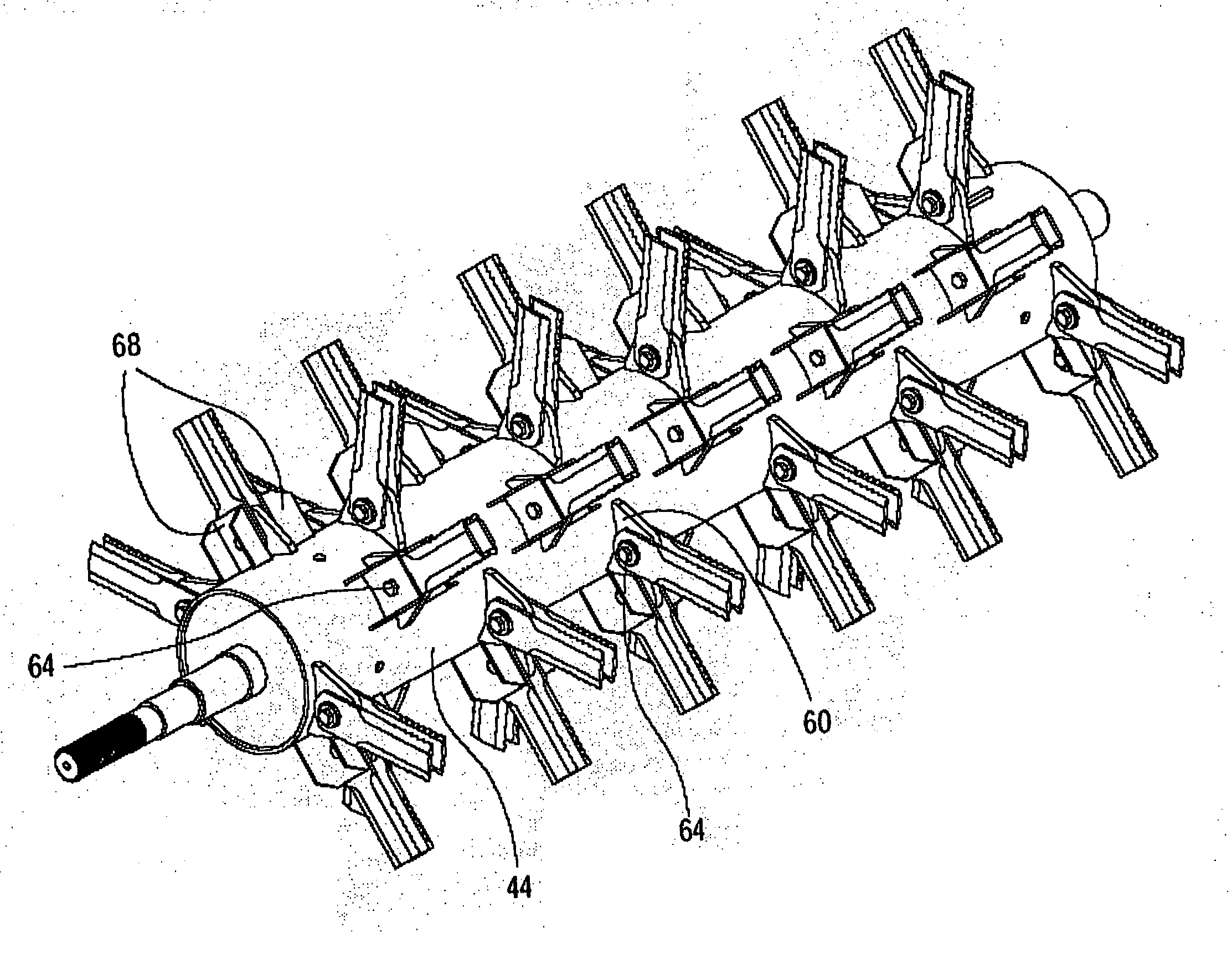
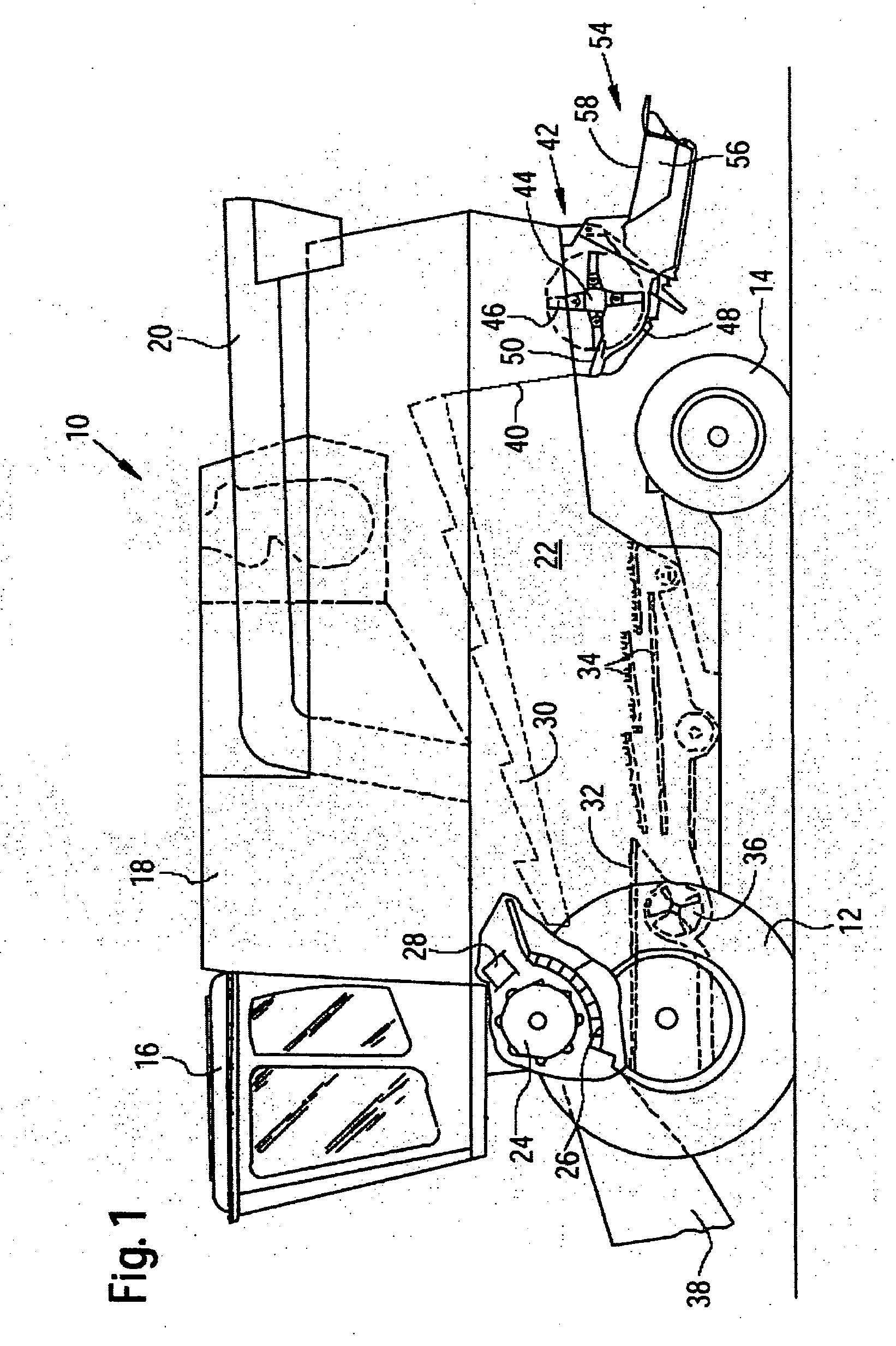
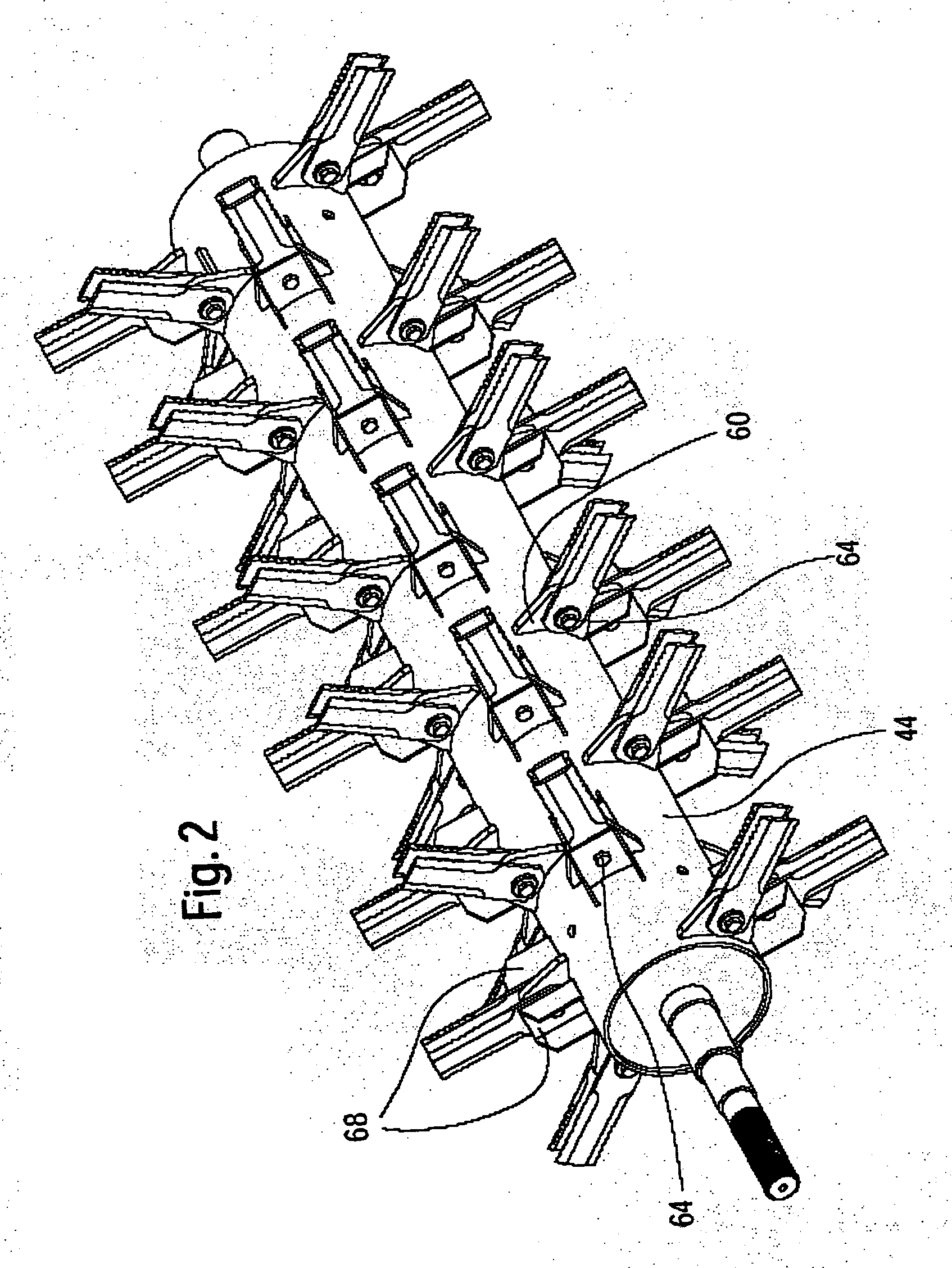
[0018] Referring now to the drawings, and more particularly to FIG. 1 there is shown a harvesting machine in the form of a combine harvester 10 carried on front driven wheels 12 and rear steerable wheels 14 and includes a driver's cab 16, from where a driver may operate it. To the rear of driver's cab 16 a grain tank 18 is connected, which may discharge crop fed to it, to the outside by way of a discharge pipe 20. Grain tank 18 is seated on a frame 22. Harvested crop is fed through threshing cylinder 24, a concave 26 and a turning drum 28 and is separated into its larger and smaller components. On subsequent shakers 30 as well as on a processing floor 32 and sieves 34 the harvested crop is separated further, wherein finally the threshed good portion is conveyed into grain tank 18. The large crop parts are conveyed across shakers 30 via a straw guiding plate 40 to a straw chopper 42. Light-weight components are blown from sieves 34 on the floor or into the inlet of straw chopper 42 b...


PUM


Abstract

A rotor for a straw chopper includes a rotor body, a mount disposed on the rotor body, at least one copper blade suspended, detachably, in a swinging fashion on the mount with a fastening element, and a fan blade element detachably connected to the mount by way of the fastening element. The fan blade element is attached in a rigid manner to the rotor body.

Description

FIELD OF THE INVENTION [0001] The invention relates to a rotor for a straw chopper of a combine harvester. BACKGROUND OF THE INVENTION [0002] Straw choppers on combine harvesters are typically equipped with a rotor having chopper blades suspended in a swinging fashion. The blades rotate at a high speed and enter into clearances defined by stationary counter-blades. The conveyed and chopped material, which may be straw or chaff or a mixture thereof, is conveyed, after being cut through the rotating chopper blades, from the housing of the straw chopper. It then meets with guiding plates disposed downstream from the straw chopper, which deflect the material laterally, allowing it to be distributed across the largest possible part of the cutting width of the combine. [0003] Combine harvesters are presently equipped with ever increasing cutting widths, which make it more and more difficult to spread the material across the cutting width of the combine harvester using such a chopper rotor...

Claims


Application Information

Patent Timeline
Patent Type & Authority Applications(United States)
IPC IPC(8): A01F12/40A01F29/09
CPCA01F12/40
Inventor LAUER, FRITZ K.
Owner DEERE & CO
Why Eureka
Try Eureka