
Systems and methods for cooling bearings

a technology of cooling bearings and systems, applied in bearing cooling, liquid fuel engines, machines/engines, etc., can solve the problems of application not previously economically or practically possible, and the gas temperature drop is substantial, so as to maximize the convective heat transfer, prolong the service life, and reduce the gas temperature.

Active Publication Date: 2010-07-13
P10 IND INC
View PDF6 Cites 4 Cited by
  • Summary
  • Abstract
  • Description
  • Claims
  • Application Information

AI Technical Summary

Benefits of technology

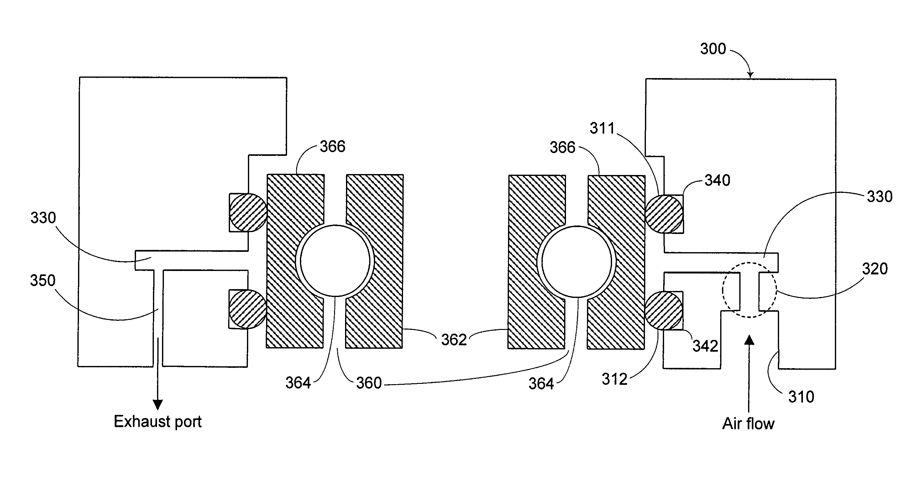
[0008]In accordance with the principles of the present invention, systems and methods are provided for cooling bearings or other objects. Such cooling may be accomplished by expanding a compressed gas in a cooling channel surrounding a bearing and allowing the expanded air to come into direct contact with the bearing, or more particularly, the outer race of the bearing. Expanding a compressed gas in local proximity of the bearing takes advantage of the Joule-Thompson expansion of gas, resulting in a substantial drop in gas temperature. The higher temperature differential between the bearing and cooling medium, combined with direct contact with the bearing outer race helps to maximize the convective heat transfer. Cooling the bearings, and consequently, the lubrication, in this manner may extend their operational lives and enables them to operate at the desired speeds. In addition, such cooling enables use of bearings in applications not previously economically or practically possible. For example, bearing cooling according to this invention permits use of grease lubricated anti-friction bearings in high speed applications that previously resulted in severely diminished bearing performance and life.
[0009]A housing may be provided for receiving a compressed gas, expanding the compressed gas to a predetermined pressure, enabling the expanded gas to directly contact the bearing, and exhausting the expanded gas. If desired, the exhausted air may be routed to or across components of a system. In one embodiment, the housing may be used to house bearings in a turbine-generator. When the turbine-generator is operating, compressed air may be provided to the housing, expanded, and used to provide localized cooling of the bearings housed therein. If desired, the exhausted gas may be routed across various components (e.g., rotor, stator windings, etc.) of the turbine-generator to promote further cooling of the turbine-generator.
[0010]The housing and techniques for cooling bearings may be used in electrical generation systems such as backup and continuously operating TACAS and CAS energy generation systems. Such systems may generate power from a source of compressed gas such as a pressure tank. When power is needed, compressed gas may be released from the gas source, expanded to a predetermined pressure (which results in a Joule-Thompson cooling of the compressed gas), optionally heated, and used to drive a turbine, which in turn drives a generator to produce power. A portion of the cool compressed gas may be routed to at least one housing in the generator and / or turbine to provide localized cooling. Thus, although the compressed gas is already cool due to expansion of the compressed gas supplied by the gas source, the housing permits further expansion of the cool compressed gas, resulting in a further reduction in temperature when being applied to the bearing. Such cooling provides significant cost savings by allowing grease lubricated anti-friction bearings to be used in the generator and / or turbine for at least the expected operational life of the CAS or TACAS system.

Problems solved by technology

Expanding a compressed gas in local proximity of the bearing takes advantage of the Joule-Thompson expansion of gas, resulting in a substantial drop in gas temperature.
In addition, such cooling enables use of bearings in applications not previously economically or practically possible.

Method used


Image

  • Systems and methods for cooling bearings
  • Systems and methods for cooling bearings
  • Systems and methods for cooling bearings

Examples


Embodiment Construction

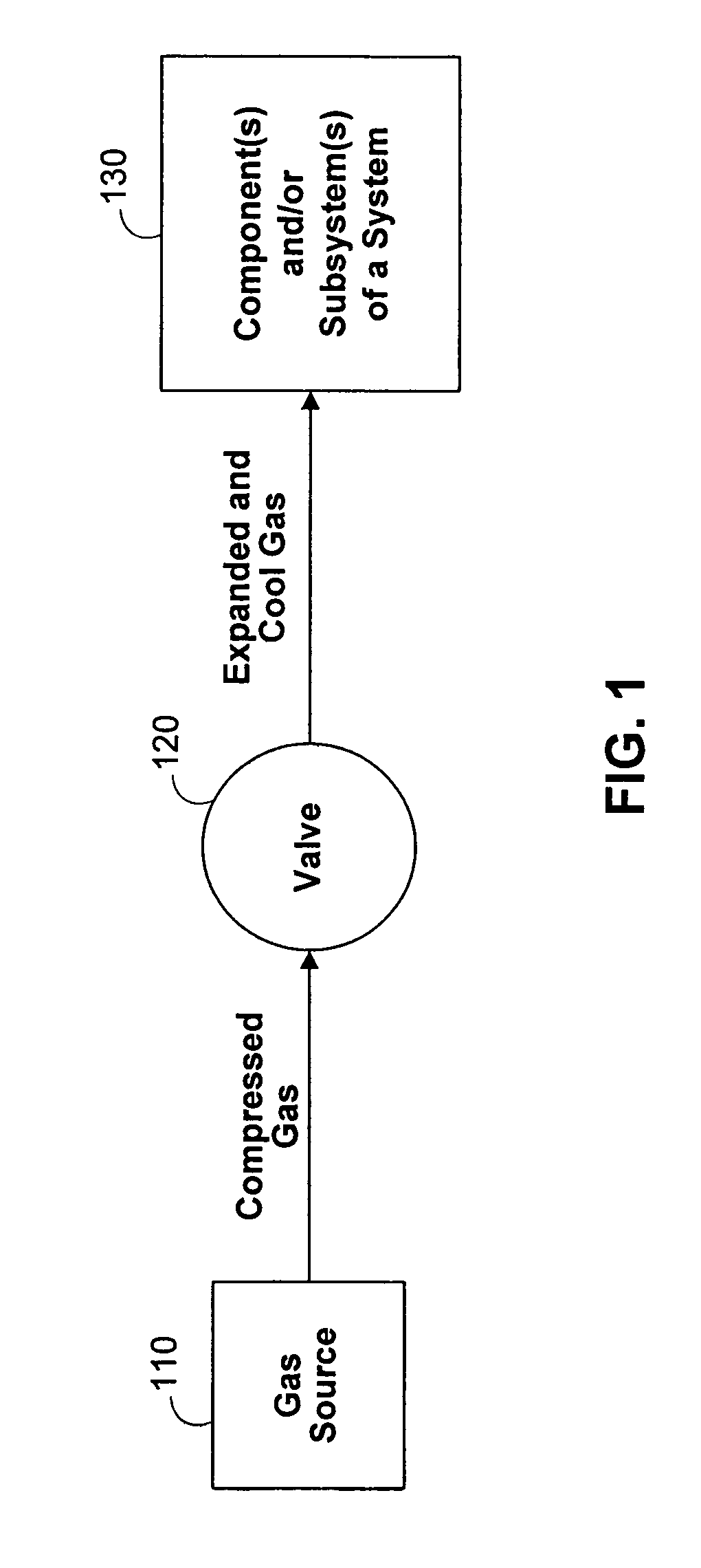
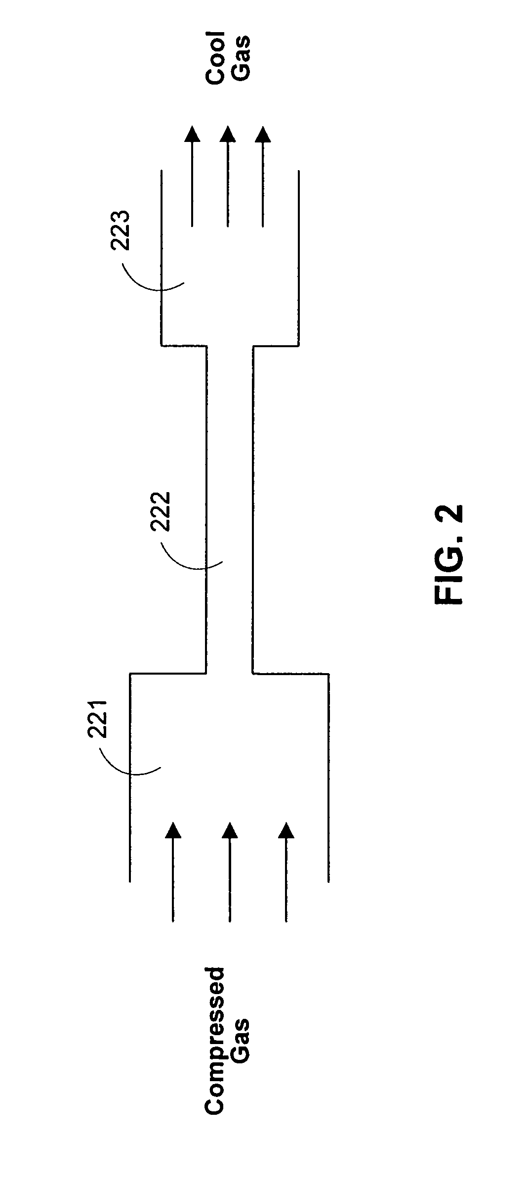
[0025]FIG. 1 is a block diagram illustrating how cool gas can be derived and used to cool bearings and / or other components of a system in accordance with the principles of the present invention. Cool gas is obtained by expanding gas from a high to low pressure. This high-to-low pressure drop results in a Joule-Thompson expansion of gas that results in a substantial drop in gas temperature. For example, expansion of gas from a relatively high pressure (e.g., 4500 PSIA) to a lower pressure (e.g., 400 PSIA) can result in gas temperatures of thirty degrees centigrade or lower. Such cool gas temperatures are much lower than temperatures achieved using conventional fans and water or oil cooling systems. As shown in FIG. 1, cool gas may be derived by expanding compressed gas provided by gas source 110 across valve 120 to a lower pressure than that of the compressed gas upstream of valve 120.

[0026]Gas source 110 may represent a point in a gas flow path having gas at a higher pressure than a...


PUM


Abstract

Systems and methods are provided for cooling bearings or other objects. Such cooling may be accomplished by expanding a compressed gas in a cooling channel surrounding a bearing and allowing the expanded air to come into direct contact with the bearing. Expanding a compressed gas in local proximity of the bearing takes advantage of the Joule-Thompson expansion of gas, resulting in a substantial drop in gas temperature, thereby maximizing the cooling potential of the gas being directly applied to the bearing. Cooling bearings in this manner extends their operational life and enables them to operate at the desired speeds. A housing may be provided for receiving a compressed gas, expanding the compressed gas to a predetermined pressure, enabling the expanded gas to directly contact the bearing, and exhausting the expanded gas.

Description

BACKGROUND OF THE INVENTION[0001]This invention relates to systems and methods for removing heat from a system, and in particular, removing heat from bearings or other objects.[0002]Bearings, bushings, and other points of support are used for many different applications requiring support for a rotating body. An example of one such application is an electrical machine such as a generator and / or motor. The rotor of such machines are typically mounted between two bearings, which bear the load of the rotor. During operation of the electric machine, heat may be generated by the stator core, stator windings, bearings, rotor, rotor windings and other sources. Heat may be detrimental to machine performance and operational life. For example, excess heat can decrease the flux capacity of permanent magnets in the machine and damage machine components such as bearings and windings (e.g., stator and rotor windings). In additional respect to bearings, lubricants contained therein may be subject t...

Claims


Application Information

Patent Timeline
Patent Type & Authority Patents(United States)
IPC IPC(8): F04D29/08
CPCF04D29/08F16C2380/26F01D15/10F01D25/125F16C37/007F04D29/059F04D29/584H02K5/173H02K5/1732H02K9/08F05D2250/82H02K2209/00F16C19/06
Inventor KECK, JAMES A.HUDSON, DONALD M.PETERSON, PAUL C.
Owner P10 IND INC
Learn More