Laparoscopic instrument and cannula assembly and related surgical method

a cannula and instrument technology, applied in the field of surgical instruments and surgical port assemblies, can solve the problems of reducing video quality, poor durability, and high cost of the instruments used for mini-laparoscopic procedures, and achieve the effect of improving the degree of freedom of the instruments

Inactive Publication Date: 2010-07-13
TYCO HEALTHCARE GRP LP
View PDF50 Cites 185 Cited by
  • Summary
  • Abstract
  • Description
  • Claims
  • Application Information

AI Technical Summary

Benefits of technology

[0008]An object of the present invention is to provide an improved port assembly for facilitating access to internal organs of a patient during laparoscopic procedures.
[0010]An additional object of the present invention is to provide improved laparoscopic instruments for facilitating operations through the umbilicus.
[0012]The present invention facilitates the performance of laparoscopic surgical procedures wherein several laparoscopic instruments are inserted into a patient through respective cannulas all extending through the same opening in the patient, for instance, through the umbilicus. The advantages of such an operation include minimizing trauma to the patient and accelerating the patient recovery.
[0025]The proximal end portion, the middle portion and the distal end portion of the instrument shaft are each substantially rigid throughout so that they cannot be bent. In one embodiment of the invention, the instrument shaft has a hockey-stick shape. Two laparoscopic surgical instruments each having a hockey stick shape are advantageously used in a crossed configuration, which markedly improves the degrees of freedom of the instruments, particularly during lateral (medial-lateral) movements.

Problems solved by technology

However, instruments used for mini-laparoscopic procedures are generally more expensive and fragile.
Because of their performance limitations, due to their smaller diameter (weak suction-irrigation system, poor durability, decreased video quality), mini-laparoscopic instruments can generally be used only on selected patients with favorable anatomy (thin cavity wall, few adhesions, minimal inflammation, etc.).
In addition, smaller, 2-3 mm, incisions may still cause undesirable cosmetic outcomes and wound complications (bleeding, infection, pain, keloid formation, etc.).
This interference greatly reduces the surgeon's ability to perform a described procedure.

Method used


Image

  • Laparoscopic instrument and cannula assembly and related surgical method
  • Laparoscopic instrument and cannula assembly and related surgical method
  • Laparoscopic instrument and cannula assembly and related surgical method

Examples


Embodiment Construction

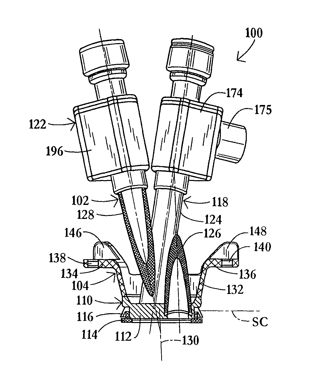
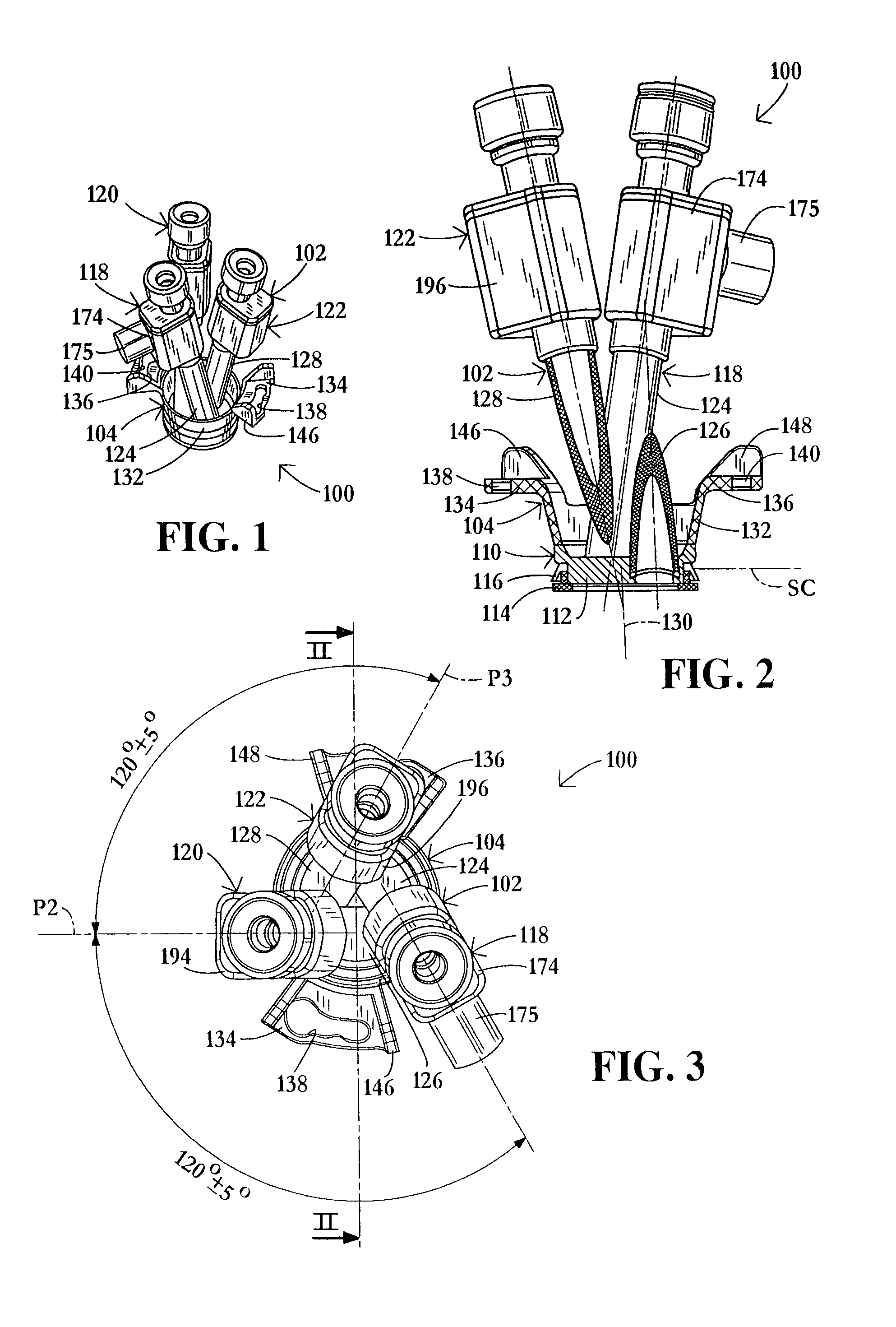
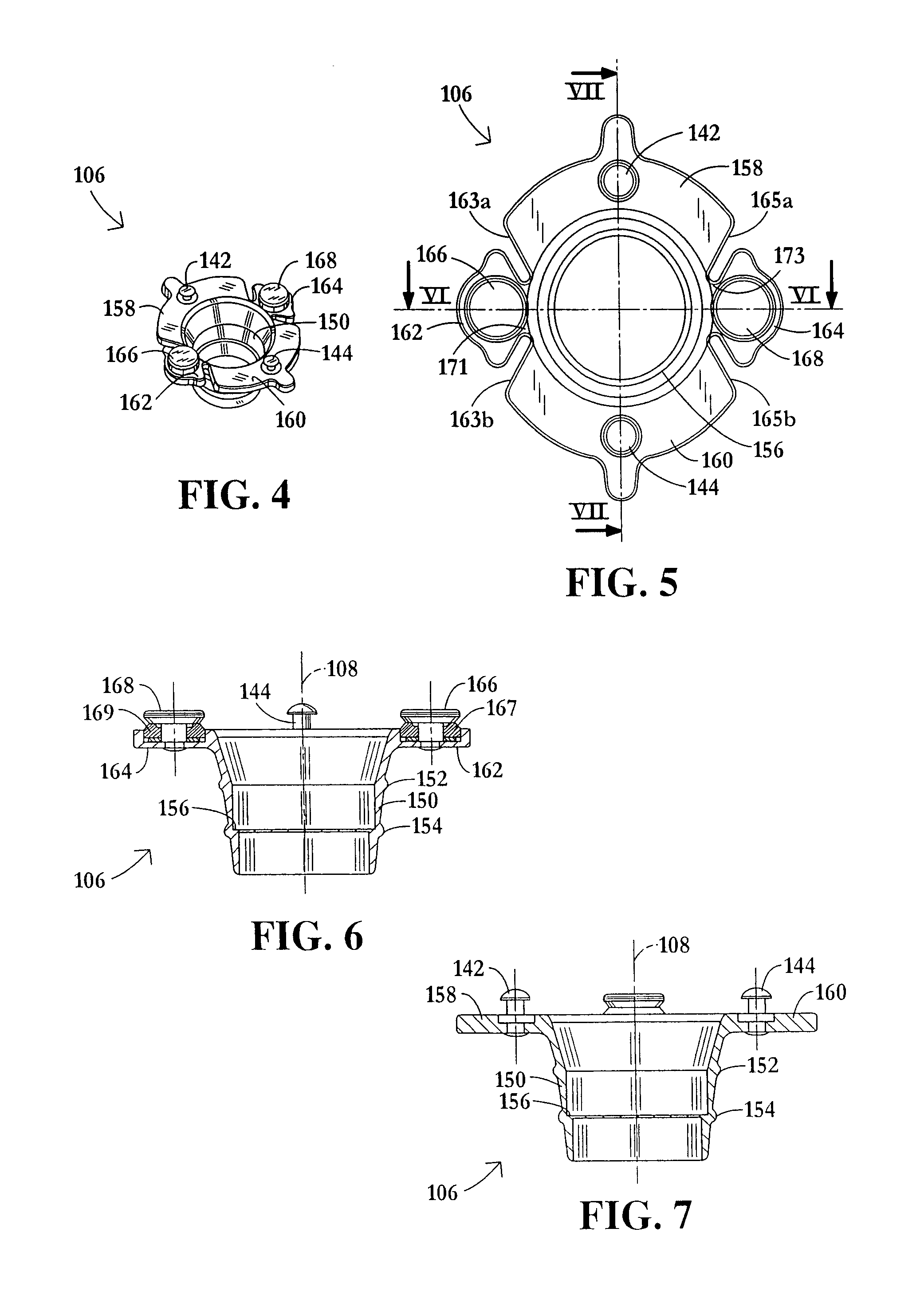
[0055]As depicted in FIGS. 1-3, a laparoscopic port or cannula assembly 100 comprises a cannula unit 102 and a connector 104 associated therewith for removably fastening the cannula unit to an annular port holder 106 (FIGS. 4-8 and 10) that is disposed in an opening (e.g., formed in the umbilicus) in a patient. Cannula unit 102 is coupled to port holder 106 by connector 104 so as to permit rotation of cannula unit 102 about a longitudinal axis 108 (FIGS. 7 and 10) of holder 106. Holder 106 has an inner side facing inside the patient and an outer side facing outside the patient during a laparoscopic procedure, and axis 108 traverses the holder from the inner side to the outer side thereof.

[0056]Cannula unit 102 comprises a base or frame 110 that is insertable into and removably attachable to port holder 106. Base or frame 110 includes a base member in the form of a planar panel or wall 112 that defines a closure surface or plane SC extending, during a laparoscopic surgical procedure,...


PUM


Abstract

A laparoscopic port assembly includes a cannula unit including three cannulas each extending at an acute angle relative to a base. The cannulas are flexible for receiving respective angulated laparoscopic instruments. The cannula unit is rotatingly received in a port holder for rotation about a longitudinal axis of the holder, the holder being disposable in an opening in a patient's skin.

Description

FIELD OF THE INVENTION[0001]The present invention relates to surgical instruments, surgical port assemblies, and an associated method. The instruments, port assemblies and method are particularly useful in the performance of laparoscopic procedures entirely through the umbilicus.BACKGROUND OF THE INVENTION[0002]Abdominal laparoscopic surgery gained popularity in the late 1980's, when benefits of laparoscopic removal of the gallbladder over traditional (open) operation became evident. Reduced postoperative recovery time, markedly decreased post-operative pain and wound infection, and improved cosmetic outcome are well established benefits of laparoscopic surgery, derived mainly from the ability of laparoscopic surgeons to perform an operation utilizing smaller incisions of the body cavity wall.[0003]Laparoscopic procedures generally involve insufflation of the abdominal cavity with C02 gas to a pressure of around 15 mm Hg. The abdominal wall is pierced and a 5-10 mm in diameter strai...

Claims


Application Information

Patent Timeline
Patent Type & Authority Patents(United States)
IPC IPC(8): A61M1/00A61M5/178A61F11/00
CPCA61B17/0218A61B17/3421A61B17/3423A61B17/3462A61B17/3403A61B17/2909A61B17/3498A61B2017/2904A61B2017/2905A61B2017/292A61B2017/2929A61B2017/3445A61B2017/3447A61B2017/3449A61B2017/3466A61B2017/347A61B2017/3492A61B2017/3419
Inventor PISKUN, GREGORYKONIK, ANATOLYROTTENBERG, DAN
Owner TYCO HEALTHCARE GRP LP
Why Eureka
Try Eureka