Reduction of biuret and free ammonia during a method for producing fertilizer granulates containing urea

Inactive Publication Date: 2010-07-13
UHDE GMBH
View PDF25 Cites 9 Cited by
  • Summary
  • Abstract
  • Description
  • Claims
  • Application Information

AI Technical Summary

Benefits of technology

[0012]The objective of the present invention is to provide an economically advantageous

Problems solved by technology

Since the use of the self-regulating centrifugal pump reduces the formation of bi

Method used


Image

  • Reduction of biuret and free ammonia during a method for producing fertilizer granulates containing urea
  • Reduction of biuret and free ammonia during a method for producing fertilizer granulates containing urea
  • Reduction of biuret and free ammonia during a method for producing fertilizer granulates containing urea

Examples


Example

DETAILED DESCRIPTION OF THE DRAWING

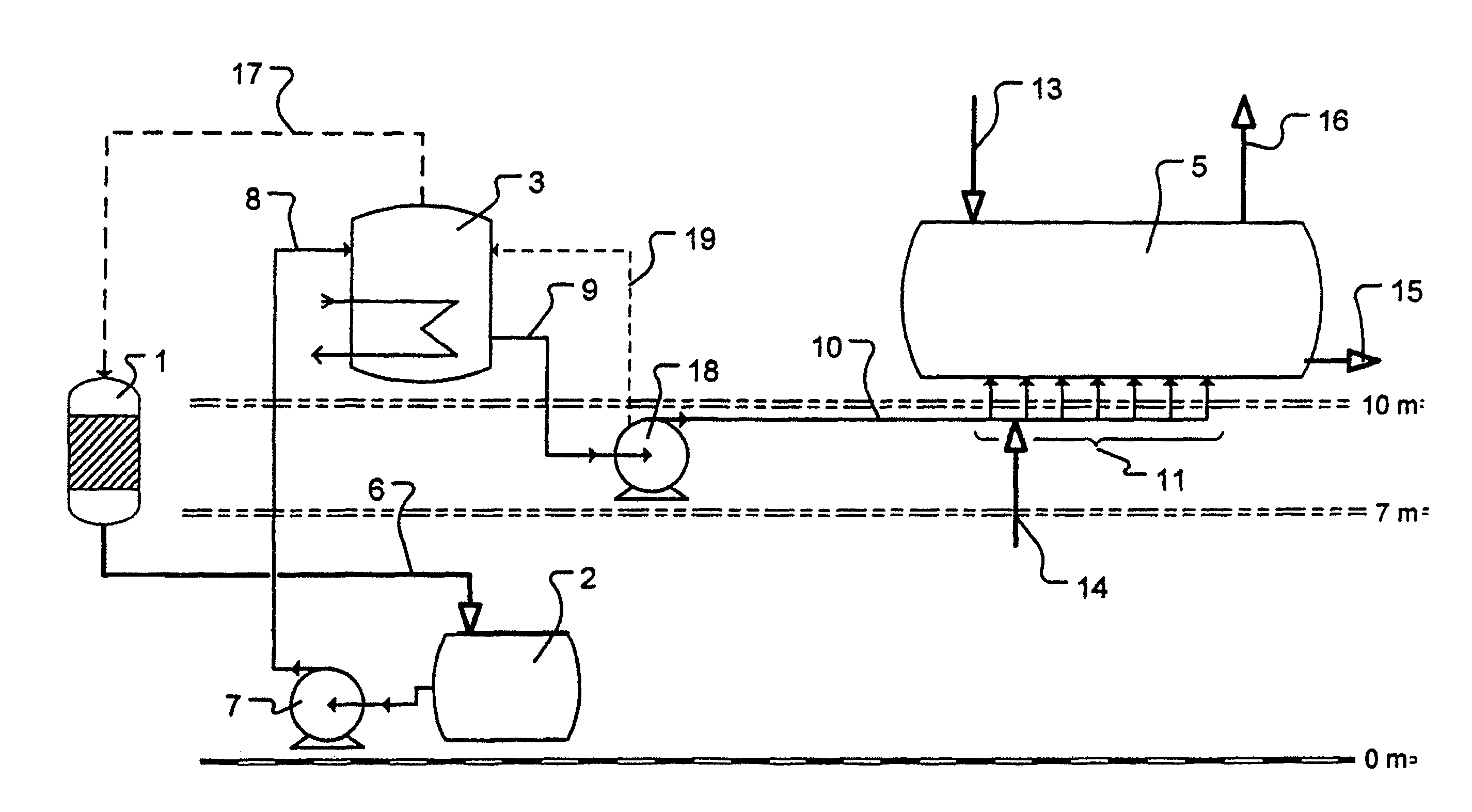
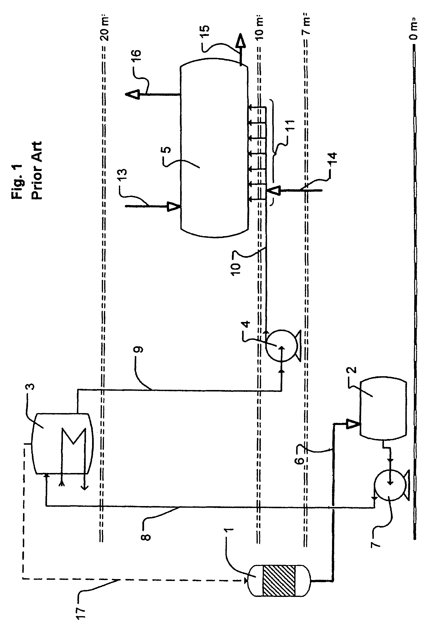
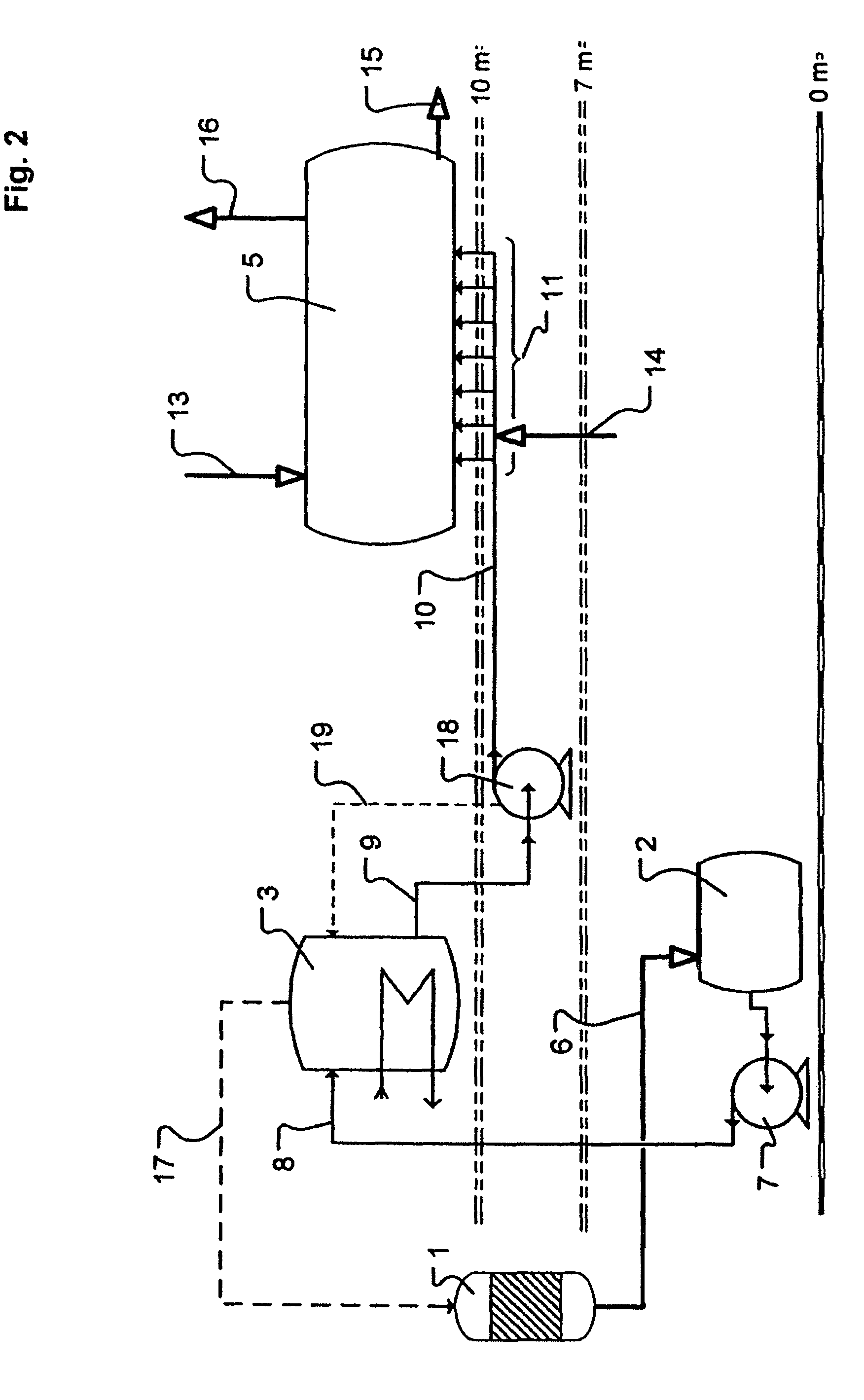
[0024]As can be seen in FIG. 1, the product formed in the synthesis stage 1 is passed via the line path 6 into a feed vessel 2, from which it is conveyed by means of a pump 7 in the line 8 from the floor level into the evaporator 3, which stands on the 20 m platform. The water vapor expelled in the evaporator 3, and also the free ammonia and other gaseous components, are returned via the pipeline 17 to the synthesis stage.

[0025]The concentrated urea solution leaves the evaporator via the pipeline 9, the suction line of the centrifugal pump 4. The difference in height which is overcome by the line 9 in the direction of the downcomer section ensures compliance with the required intake pressure or NPSH value of the centrifugal pump 4, which is positioned at a height of about 7 m. In the pipeline 10, the pressure line of this centrifugal pump 4, this solution is conveyed into the header system 11 of the granulator 5, the granulator 5 being positioned a...


PUM

PropertyMeasurementUnit
Levelaaaaaaaaaa

Abstract

The invention relates to a method for producing a fertilizing agent containing urea, by means of synthesis step, an evaporation process, and a granulation unit. According to said method, a self-regulating centrifugal pump is used to reduce the dwell time and to optimize the positioning of the components of the method for transporting the product flow of the evaporation process to the granulation unit.

Description

BACKGROUND OF THE INVENTION[0001]The invention relates to a process for producing urea fertilizer by means of a synthesis stage, an evaporation unit, and a granulation unit, wherein a self-regulating centrifugal pump is used to reduce the residence time and optimize the positioning of the process components for conveying the product stream from the evaporating operation to the granulation unit.[0002]Processes for producing granulated fertilizers have been extensively described in the technical and patent literature, for which U.S. Pat. No. 6,203,730 B1, DE 28 25 039 B2, and U.S. Pat. No. 4,943,308 A may serve as examples. Typically the product stream, in the form of a melt or solution, arriving from the synthesis stage, is supplied to an evaporator, for the purpose of adjusting the water content, and then passed into the granulation stage. In certain prior-art processes, introduction into the granulator is preceded by mixing with a fine solid fraction, which is generally recycled gr...

Claims


Application Information

Patent Timeline
IPC IPC(8): C05C9/00B01J2/04C05G3/00
CPCC05C9/005C05G3/0058C05G5/12
Inventor LEOPOLD, EUGEN
Owner UHDE GMBH
Why Eureka
Try Eureka