Reducing contrails during operation of aircraft

Pending Publication Date: 2021-01-07
MTU AERO ENGINES GMBH
View PDF0 Cites 3 Cited by
  • Summary
  • Abstract
  • Description
  • Claims
  • Application Information

AI Technical Summary

Benefits of technology

[0010]It is a technical object of the present invention to provide a method which makes possible a reduct

Problems solved by technology

Combusting these fuels results in undesirable environmental impacts that contribute to climate change.
There are contentious discussions among experts about the effect of contrails and of the resulting c

Method used


Image

  • Reducing contrails during operation of aircraft
  • Reducing contrails during operation of aircraft

Examples


Example

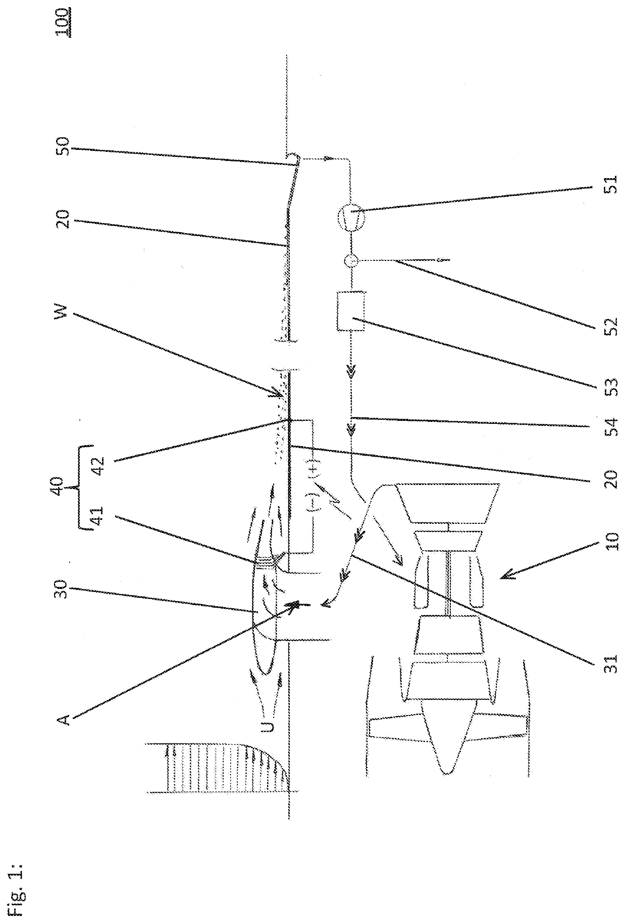
[0031]FIG. 1 schematically shows a first exemplary embodiment of an aircraft 100 according to the present invention. The aircraft, which is suited, in particular for implementing a method according to the present invention, encompasses a heat engine 10 for propelling aircraft 100 as well as a conduit system 31 schematically illustrated in the figure that is adapted for conducting exhaust gas A from the heat engine to a nozzle 30.

[0032]In the illustrated operation of the aircraft (in the region of a boundary layer), nozzle 30 is at least partially circumflowed by ambient air U and is adapted for discharging exhaust gas A led therethrough in the direction of flow of ambient air U on a surface 20 over which the ambient air flows (thus, along which the ambient air flows). Thus, exhaust gas A and the respective portion of ambient air U mix at surface 20. The resulting gas mixture then continues to flow along surface 20.

[0033]The inventive mixing of exhaust gas A with ambient air U allows...


PUM


Abstract

A method is described for reducing contrails during operation of an aircraft (100, 100′) having a heat engine 10. The method includes inducing a condensation of moisture contained in the exhaust gas (A) of the heat engine by mixing at least a portion of the exhaust gas with ambient air (U) of the aircraft as well as separating the condensed-out water on the aircraft. Also described is an aircraft (100, 100′) having a heat engine (10). The aircraft includes at least one nozzle (30) which is adapted for conducting exhaust gas (A) from the heat engine of the aircraft at least partially into ambient air (U) of the aircraft and thus to produce a gas mixture, and at least one separator device (40) for separating condensed-out water from the gas mixture.

Description

[0001]The present invention relates to a method for reducing contrails during operation of aircraft having heat engines. The present invention also relates to an aircraft having a heat engine.BACKGROUND[0002]Many aircraft are propelled by heat engines in combination with suitable propulsion generators (propulsors). As propulsion generators, propellers and blowers (also referred to as “fans”) are used; moreover, the exhaust-gas jet from the heat engine also contributes to the propulsion.[0003]The most commonly used heat engines are gas turbines and piston engines (reciprocating pistons, rotary pistons), the latter only being used today for relatively small aircraft.[0004]Presently, fossil fuels are almost exclusively used as sources of energy. Attempts have also been made with liquid hydrogen or liquid natural gas. Combusting these fuels results in undesirable environmental impacts that contribute to climate change.[0005]Combusting fossil fuels mainly produces carbon dioxide (CO2) an...

Claims


Application Information

Patent Timeline
IPC IPC(8): B01D53/26B01D5/00B01D53/24B01D53/32F02K1/46
CPCB01D53/265B01D5/0027B01D5/0084B01D5/009B01D2259/818B01D5/0081B01D53/24B01D53/323F02K1/46B01D5/0051B64D33/04F01D25/32F02C7/00F05D2260/608B01D2258/01B01D2259/4575F05D2260/213F05D2260/609Y02T50/60
Inventor KLINGELS, HERMANN
Owner MTU AERO ENGINES GMBH
Why Eureka
Try Eureka