Ultraminiature broadband light source and method of manufacturing same

a broadband light source and ultra-miniature technology, applied in the direction of optical radiation measurement, instruments, spectrometry/spectrophotometry/monochromators, etc., can solve the problems of partial shorting of a portion of a spiral turn, increasing the length of the spiral, and affecting the quality of the light sour

Inactive Publication Date: 2010-07-13
NASA
View PDF18 Cites 18 Cited by
  • Summary
  • Abstract
  • Description
  • Claims
  • Application Information

AI Technical Summary

Benefits of technology

[0037]Accordingly, it is an object of the invention to use a commercially available package and lid in combination with a new process and new filament disclosed herein which is advantageous insofar as sealing of the package, simplicity of construction, ruggedness, durability and cost are concerned.

Problems solved by technology

Actual mechanical and electrical contact may result in partial shorting of a portion of a turn of the spiral.
If the turns are too close together this can happen due to some distortion of the spiral during operation or due to vibration.
As the inner windings tend to de-coil or unwind, their length increases and they may eventually collide with the more stationary cooler outer windings producing an electrical short path.
Although the light source of the '866 patent is a very efficient broadband light source its assembly is somewhat complicated and involves the deposition of the Ti / Pt / Au bonding rings on the top, middle and bottom layers and subsequent processing under vacuum or in an inert atmosphere at or near atmospheric pressure in a thermal compression binder to assemble the device together.

Method used


Image

  • Ultraminiature broadband light source and method of manufacturing same
  • Ultraminiature broadband light source and method of manufacturing same
  • Ultraminiature broadband light source and method of manufacturing same

Examples


Embodiment Construction

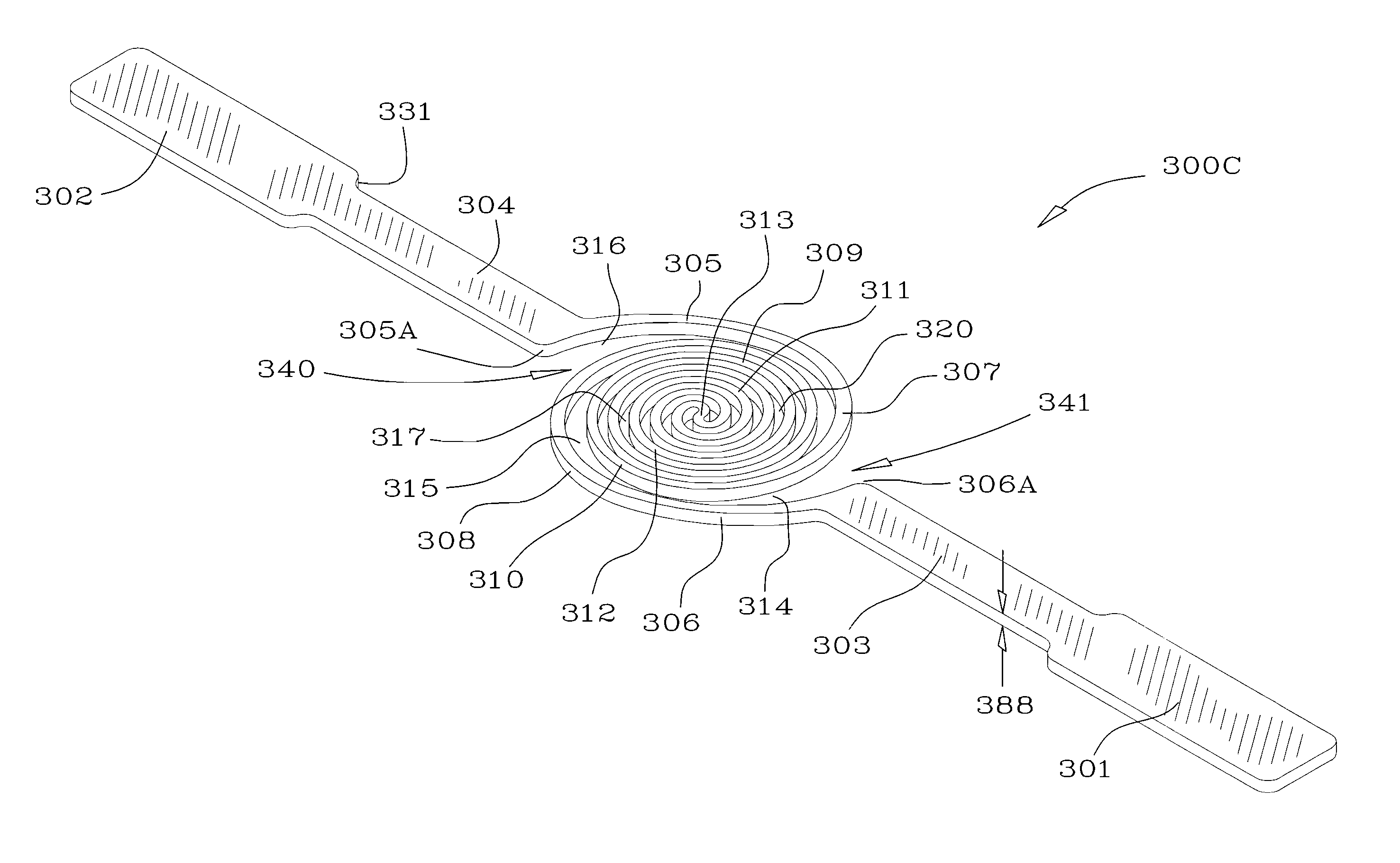
[0064]FIG. 3 is an illustration of the double-spiral element 300 of the instant invention having end contact portions 301, 302 which are divergent from the next adjacent spiral. By increasing the radius of the outer windings of the double-spiral, the inner windings are allowed to decoil while not contacting the outer windings or tabs so that the short path is less likely for a particular operating voltage. The net result is to allow more stable light output for a longer lifetime at a higher operating point for the filament.

[0065]End contact portions 301, 302 of the double-spiral filament contact ledge 405 of leadless chip carrier package 400 and are in electrical communication therewith. See, FIGS. 4 and 4A, which generally represent a commercially available leadless chip carrier package such as the one illustrated and made by Kyocera Corporation of Kyoto, Japan, Kyocera Drawing Number PB-C88231-JMI. It will be noted that the leadless chip carrier package includes a plurality of gol...


PUM


Abstract

An ultraminiature light source using a double-spiral shaped tungsten filament includes end contact portions which are separated to allow for radial and length-wise unwinding of the spiral. The double-spiral filament is spaced relatively far apart at the end portions thereof so that contact between portions of the filament upon expansion is avoided. The light source is made by fabricating a double-spiral ultraminiature tungsten filament from tungsten foil and housing the filament in a ceramic package having a reflective bottom and a well wherein the filament is suspended. A vacuum furnace brazing process attaches the filament to contacts of the ceramic package. Finally, a cover with a transparent window is attached onto the top of the ceramic package by solder reflow in a second vacuum furnace process to form a complete hermetically sealed package.

Description

ORIGIN OF THE INVENTION[0001]The invention described herein was made by an employee of the United States Government, and may be manufactured and used by the government for government purposes without the payment of any royalties therein and therefor. The invention was made under contract between the United States Government and employees of other entities and as such the United States Government has certain rights in this invention.FIELD OF THE INVENTION[0002]The invention is in the field of broadband incandescent light sources which may be used for the calibration of spectrometers and for powering optical sensors.BACKGROUND OF THE INVENTION[0003]The invention is in the field of broadband light sources used to calibrate spectrometers or supply light to other optical instruments for powering them or for other calibration and measurement purposes. Spectrometers are instruments which are used to determine spectral information about objects which indicate to scientists and engineers qua...

Claims


Application Information

Patent Timeline
Patent Type & Authority Patents(United States)
IPC IPC(8): H01J17/04H01J61/04
CPCG01J3/10H01K1/14H01K1/18H01K7/00
Inventor TUMA, MARGARET L.COLLURA, JOSEPH S.HELVAJIAN, HENRYPOCHA, MICHAEL D.MEYER, GLENN A.MCCONAGHY, CHARLES F.OLSEN, BARRY L.HANSEN, WILLIAM W
Owner NASA
Why Eureka
Try Eureka