Rearming electronic animal trap with infrared sensor and multiple-killing-plate configuration

a technology of infrared sensor and electronic animal trap, which is applied in the field of electric or electronic animal trap, can solve the problems of increased electrocution capability, decreased pest escape probability, waste of effort by exterminator personnel or other users, etc., and achieves the effect of quick and efficient electrocution of a targeted animal, low cost and simple construction

Active Publication Date: 2010-07-20
WOODSTREAM CORP
View PDF13 Cites 32 Cited by
  • Summary
  • Abstract
  • Description
  • Claims
  • Application Information

AI Technical Summary

Benefits of technology

[0015]A further object of the present invention is to provide an electronically-controlled animal trap that is able to detect the absence of an animal and thereafter to rearm itself multiple times without requiring human intervention.
[0016]Yet another object of the present invention is to provide an electronically-controlled animal trap having a detection mechanism that generates and senses an interruptible beam signal, i.e., an interruptible beam sensor. The interruptible beam sensor is effective against any incoming pest large enough to interrupt the interruptible beam signal.
[0017]A still further object of the present invention is to provide an electronically-controlled animal trap, particularly a rat trap, which will quickly and efficiently electrocute a targeted animal, is simple in construction, inexpensive to manufacture and highly reliable and completely safe in use, with reduced servicing requirements through automatic rearming and interruptible beam sensing.
[0019]As used herein, the term “interruptible beam sensor” means a detection mechanism that generates and senses an interruptible beam signal. The interruptible beam sensor increases the likelihood of rapid and reliable pest detection, both before and after the killing cycle.

Problems solved by technology

Even with the structures intended to prevent escape, larger vermin such as rats may not have been killed and may have escaped.
As a result, since the standby mode indicates the presence of a dead pest, because it was in fact initiated by a false trigger, wasted effort is expended by exterminator personnel or other users in servicing and resetting a trap which is, in fact, already empty.
The use of three plates both increases electrocution capability and decreases the likelihood of pest escape once the trap has been activated.
Because the '466 patent relies upon detecting impedance across the plates within a range which is representative of a rat, the trap may not detect undesired pests which fall outside this range.
Further, if the rat is present but is not in contact with both plates, as when the animal sits up on its haunches to investigate the roof area of the trap, its presence will not be detected.
This would be undesirable because rats are known to avoid other dead rats so that the trap would be ineffective in capturing a second rat.
In addition, the trap could “hide” the dead carcass for an extended period, exposing the surrounding area to the resulting decay and bacteria growth, since the trap would not provide the visual indicator that a dead animal is contained therein and trap service is required.

Method used


Image

  • Rearming electronic animal trap with infrared sensor and multiple-killing-plate configuration
  • Rearming electronic animal trap with infrared sensor and multiple-killing-plate configuration
  • Rearming electronic animal trap with infrared sensor and multiple-killing-plate configuration

Examples


Embodiment Construction

[0030]Although only one preferred embodiment of the invention is explained in detail, it is to be understood that the embodiment is given by way of illustration only. It is not intended that the invention be limited in its scope to the details of construction and arrangement of components set forth in the following description or illustrated in the drawings. Also, in describing the preferred embodiments, specific terminology will be resorted to for the sake of clarity. It is to be understood that each specific term includes all technical equivalents which operate in a similar manner to accomplish a similar purpose.

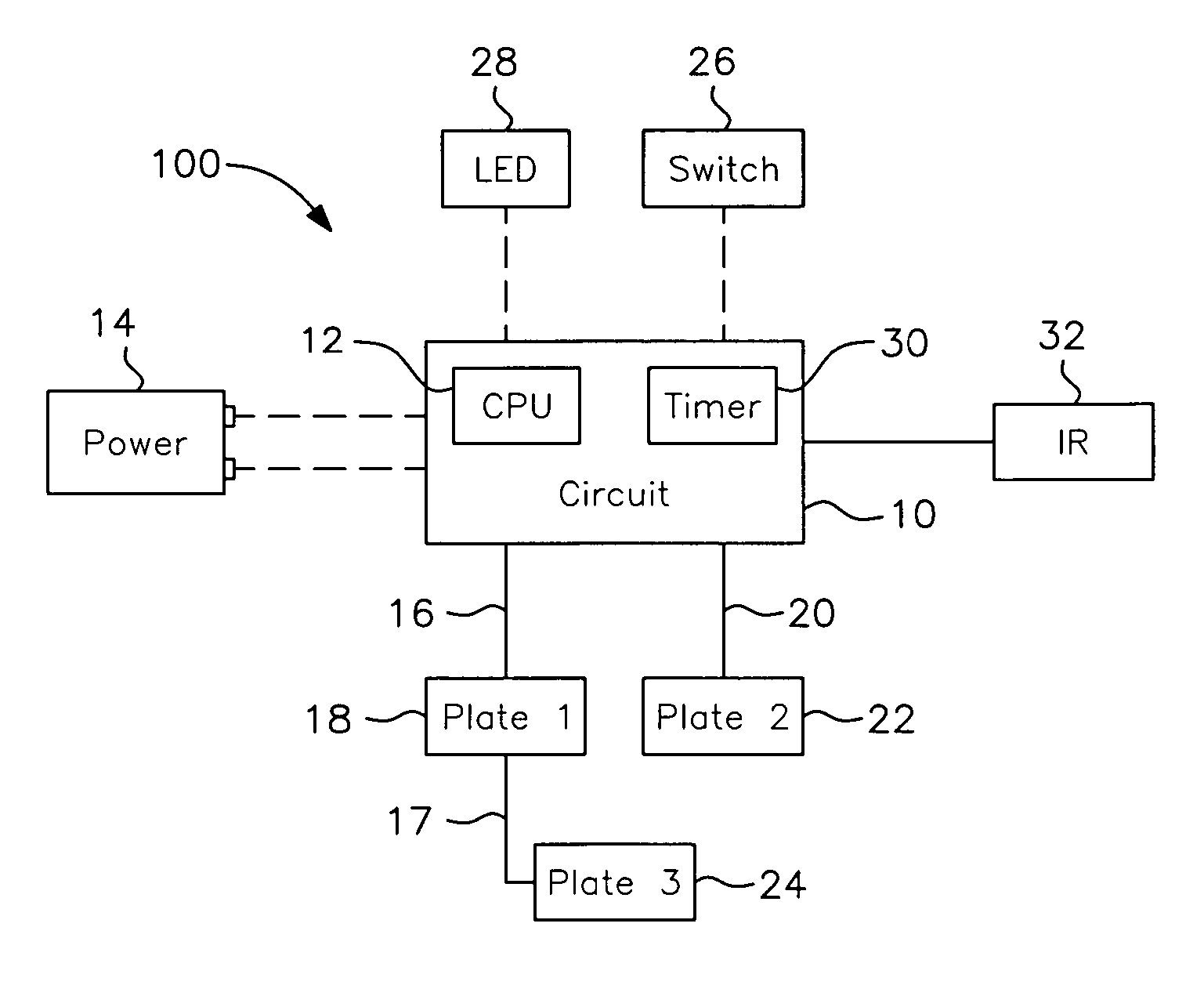
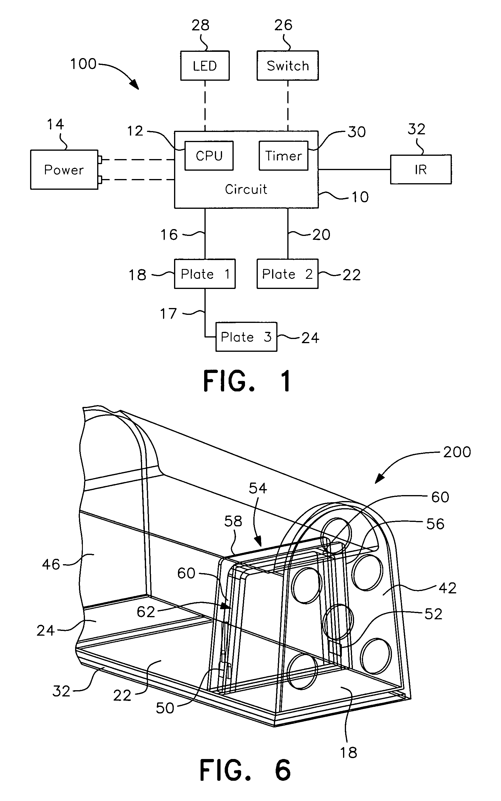
[0031]FIG. 1 is a block diagram of the rearming circuit components, generally designated by the reference numeral 100, according to the present invention. The circuit components 100 include a high-voltage output circuit 10 controlled by a central processing unit (CPU) 12 and electrically connected to a power supply 14. The CPU 12 may be embodied as a standard 8-bit micro c...


PUM


Abstract

An electric or electronic animal trap with a CPU-controlled, rearming, multiple killing plate configuration and automatically resetting interruptible beam sensor for triggering a high voltage cycle. A high-voltage output circuit is connected to killing plates which are activated with a high-voltage pulse train when a pest interrupts the beam signal, such as an infrared beam signal generated by an infrared transmitter to an infrared receiver. The trap is preferably configured to automatically rearm if the IR beam signal is no longer interrupted after the killing cycle. If the IR beam signal is still blocked after the killing cycle, however, the trap enters a standby mode indicating trap servicing is required to remove the dead rodent from the trap.

Description

BACKGROUND OF THE INVENTION[0001]1. Field of the Invention[0002]The present invention relates to electric or electronic animal traps, and relates more particularly to an animal trap adapted to catch and electrocute a targeted animal, and also to rearm in the event the continuing presence of the animal is not detected upon completion of a killing cycle.[0003]Although the concepts of the instant invention are equally applicable to traps for animals of any size, devices of this type are primarily utilized in connection with the trapping and killing of rats and the description will, therefore, focus on this application.[0004]2. Description of the Related Art[0005]A number of animal traps have been developed which include structural devices to trap an animal and prevent its escape, along with electric or electronic components which act to kill the trapped animal.[0006]One such device is found in U.S. Pat. No. 6,609,328 (“the '328 patent”, which is hereby expressly incorporated herein by ...

Claims


Application Information

Patent Timeline
Patent Type & Authority Patents(United States)
IPC IPC(8): A01M19/00
CPCA01M23/38A01M31/002
Inventor WETZEL, TROY A.CRUZ, ROBERT T.EYER, RICHARD L.
Owner WOODSTREAM CORP
Why Eureka
Try Eureka