Anti-clogging fuel pump module

a fuel pump and module technology, applied in the direction of liquid fuel feeders, machines/engines, feed systems, etc., can solve the problem of reducing the capture of fine sediment particles

Inactive Publication Date: 2010-07-20
GM GLOBAL TECH OPERATIONS LLC
View PDF26 Cites 12 Cited by
  • Summary
  • Abstract
  • Description
  • Claims
  • Application Information

AI Technical Summary

Benefits of technology

[0009]The present invention is a by-pass fuel system in which the plumbing of the fuel pump module is configured such that the by-pass strained fuel remains separate from the reservoir fuel after by-pass such that it is not re-strained before re-entry to the fuel pump.
[0010]The anti-clogging fuel pump module according to the present invention is plumbed to ensure the by-pass strained (and filtered) fuel is directed to the fuel pump separately with respect to the reservoir fuel, wherein it never mixes with reservoir fuel except after the reservoir fuel has passed through the strainer. Thus, the by-pass strained fuel only mixes with strained fuel from the strainer before its entry to the fuel pump. Accordingly, only reservoir fuel in the fuel pump module is passed through the strainer, whereby the clogging rate of the strainer is minimized.
[0011]A benefit of the anti-clogging fuel pump module is that it allows the fuel pump to preferentially utilize the by-pass strained fuel, thereby reducing the relative flow rate of the fuel pump reservoir fuel (unstrained fuel) through the strainer attached to the fuel pump. This reduction in the reservoir fuel (unstrained and potentially “dirty” fuel) flow through the strainer will reduce the capture of fine sediment particles in and on the strainer, wherein such particles tend to clog the strainer. Other benefits of the present invention include a potential cleaning effect of the outer surface of the strainer by flow of the by-pass strained fuel, a potential reduction of fuel pump wear, an improvement in the hot fuel handling capabilities of the fuel pump by increasing the fuel pressure (reducing fuel vapor formation in the fuel pump) at the inlet of the pump, and reduction of the volatility of the fuel due to direct recirculation of strained fuel and vapor stripping of the fuel being pumped.
[0012]Accordingly, it is an object of the present invention to provide a by-pass fuel system in which the plumbing of the fuel pump module is configured such that the by-pass strained fuel remains separate from the reservoir fuel after by-pass such that it is not re-strained before re-entry to the fuel pump.

Problems solved by technology

This reduction in the reservoir fuel (unstrained and potentially “dirty” fuel) flow through the strainer will reduce the capture of fine sediment particles in and on the strainer, wherein such particles tend to clog the strainer.

Method used


Image

  • Anti-clogging fuel pump module
  • Anti-clogging fuel pump module
  • Anti-clogging fuel pump module

Examples


Embodiment Construction

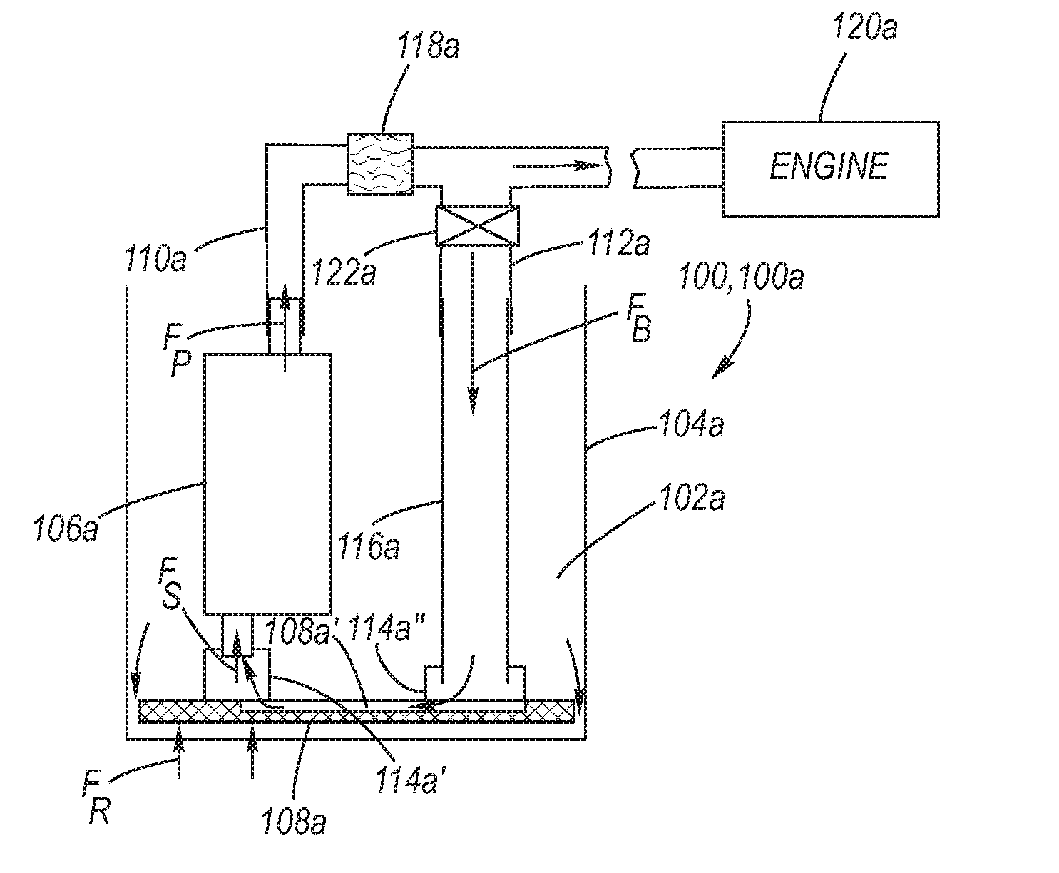
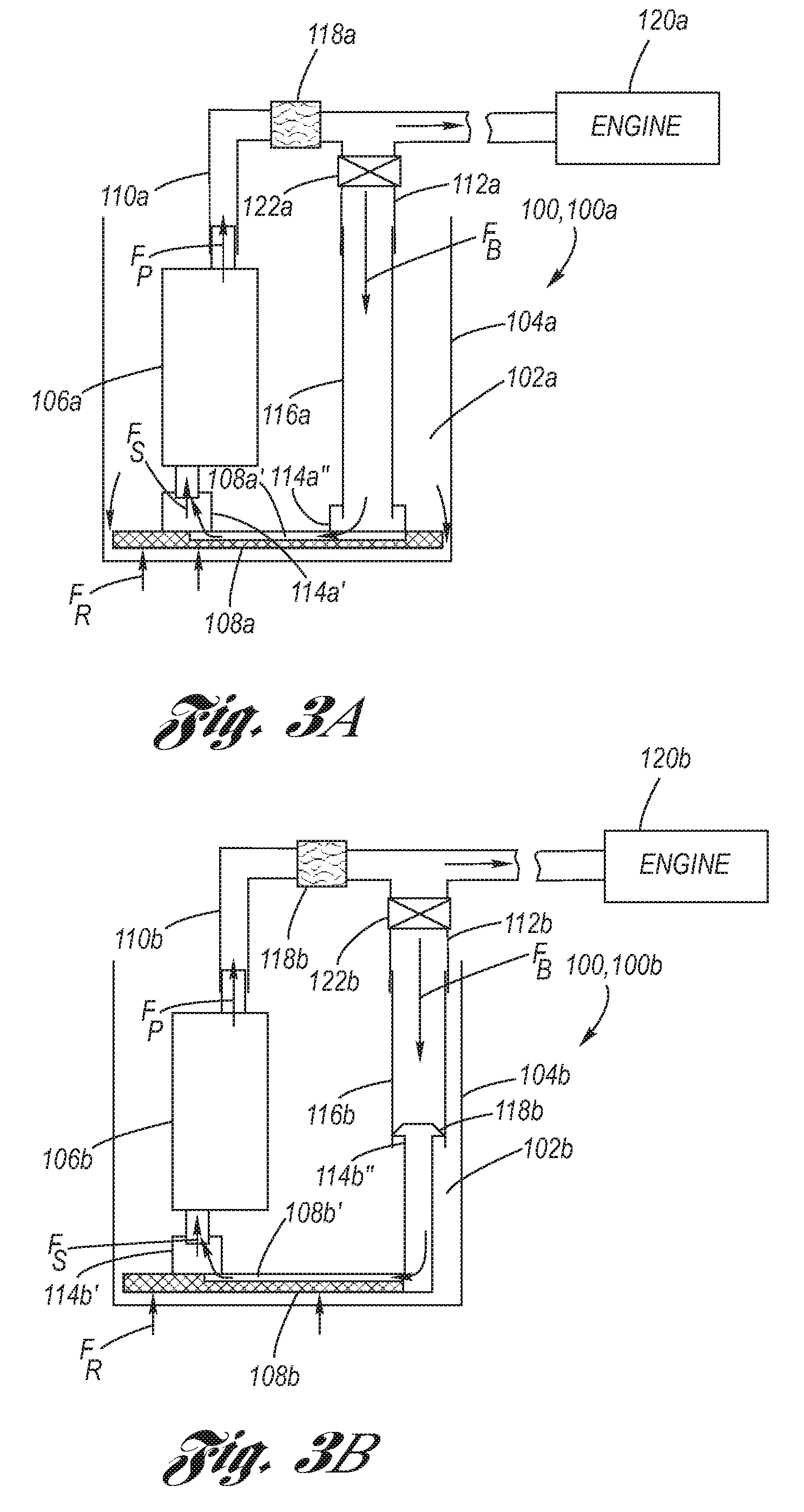
[0022]Referring now to the Drawing, FIGS. 3A through 5 depict various aspects of an anti-clogging fuel pump module 100 for a fuel tank of a by-pass fuel system, wherein the by-pass strained fuel remains separate from the reservoir fuel (i.e., it retains its unique identity) after by-pass such that it is not mixed with the reservoir fuel upstream of the strainer, but rather mixed with strained fuel downstream of the strainer before delivery to (i.e., upstream of) the fuel pump.

[0023]Referring now to FIG. 3A, a first schematic example of the anti-clogging fuel pump module 100, 100a is depicted, utilized as for example in the manner of fuel pump module 14 in FIG. 1 with respect to a fuel tank of a by-pass fuel system.

[0024]The fuel pump module 100a has a module reservoir 102a defined by a plastic module sidewall 104a. Strained fuel FS which has passed through a strainer 108a is pumped by a fuel pump 106a, and delivered as strained pumped fuel FP to the engine 120a via an in-line fuel f...


PUM


Abstract

A by-pass fuel system in which the plumbing of the fuel pump module is configured to ensure by-pass strained (and filtered) fuel remains separate from the reservoir fuel after by-pass such that it is not re-strained before re-entry to the fuel pump. The anti-clogging fuel pump module is plumbed such that the by-pass strained fuel is directed to the fuel pump separately with respect to the reservoir fuel, wherein it never mixes with reservoir fuel except after the reservoir fuel has passed through the strainer. Thus, the by-pass strained fuel only mixes with strained fuel from the strainer before its entry to the fuel pump. Accordingly, only reservoir fuel in the fuel pump module is passed through the strainer, whereby the clogging rate of the strainer is minimized.

Description

TECHNICAL FIELD[0001]The present invention relates to fuel pump modules which are interfaced with fuel tanks for motor vehicles, and more particularly to a by-pass fuel system in which strained (and filtered) by-pass fuel is sent directly to the fuel pump without being re-strained.BACKGROUND OF THE INVENTION[0002]Motor vehicle fuel tanks provide not only a reservoir for fuel but also must have accommodation for adding fuel, delivering fuel (i.e., to the engine) and monitoring the amount of the fuel therein. It has become a common practice to combine the fuel delivery and monitoring functions via a fuel pump module which is removably interfaced with an opening of the fuel tank outershell.[0003]FIG. 1 depicts an example of a motor vehicle fuel tank 10 having, by way of example, a saddle shape featuring two fuel sumps 10a, 10b. The fuel tank outershell 12 is provided with first and second openings 12a, 12b, each opening being disposed over a respective fuel sump 10a, 10b. At the first ...

Claims


Application Information

Patent Timeline
Patent Type & Authority Patents(United States)
IPC IPC(8): F02M37/04
CPCF02M37/0094F02M37/106
Inventor VILLAIRE, WILLIAM L.HALSALL, ROBERTHART, MITCHELL E.
Owner GM GLOBAL TECH OPERATIONS LLC
Why Eureka
Try Eureka