Implant delivery device

Inactive Publication Date: 2010-07-20
ANGIOMED GMBH & CO MEDIZINTECHNIK KG
View PDF102 Cites 114 Cited by
  • Summary
  • Abstract
  • Description
  • Claims
  • Application Information

AI Technical Summary

Benefits of technology

[0021]It is one object of the present invention to provide a system for delivering self-expanding stents to stenting sites within the body, which minim

Problems solved by technology

Particles of tissue, once detached, could be carried away in the flow of bodily fluid within the lumen, conceivably with adverse or even fatal consequences.
If that distal end includes surfaces which could engage bodily lumen wall tissue and cause it to detach from the wall, or at least weaken the conne

Method used


Image

  • Implant delivery device
  • Implant delivery device
  • Implant delivery device

Examples


Embodiment Construction

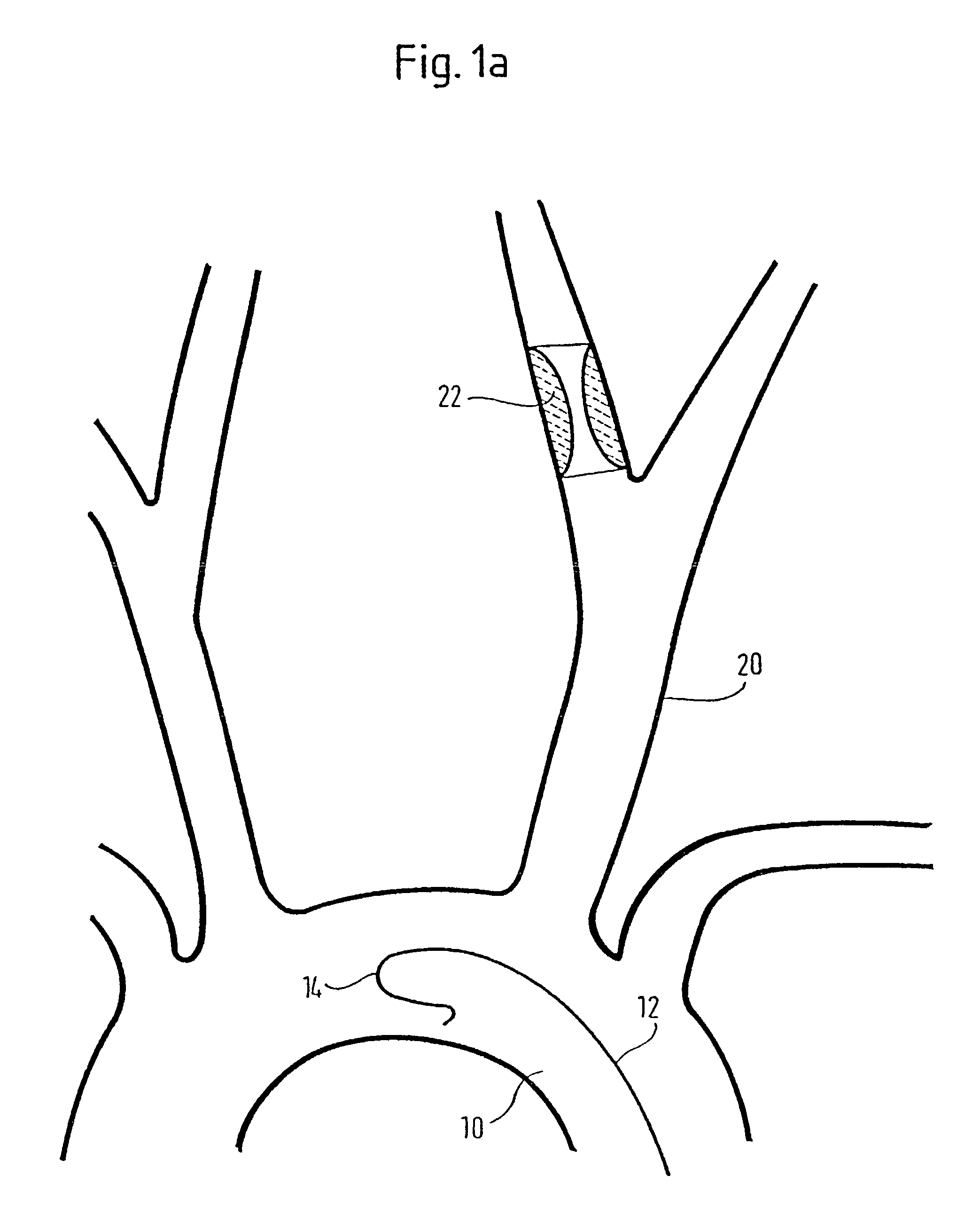
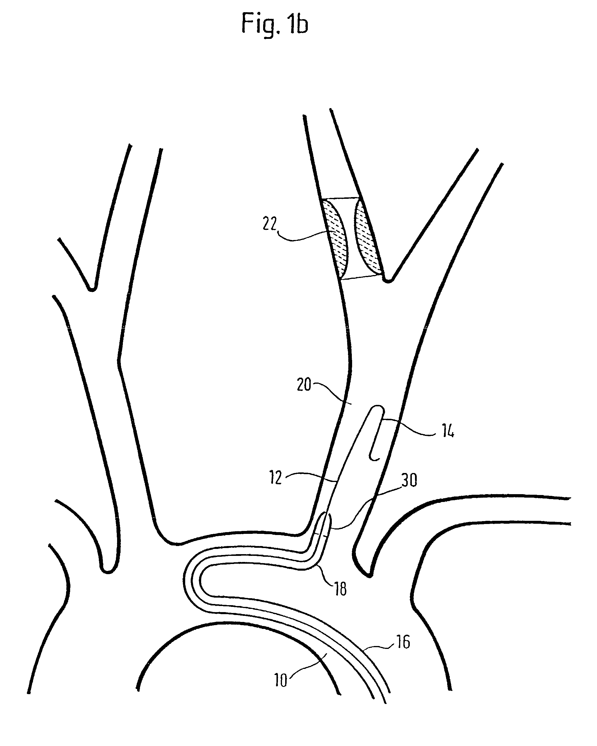
[0059]Referring first to FIG. 1a, there is shown in the aortic arch 10 a guidewire 12 with a configured tip portion 14. In FIG. 1b a catheter 16, with a figurated tip portion 18 of its length, has been advanced along the guidewire 12 and the guidewire and catheter have been manipulated to bring them into the right carotid artery (CA) 20. The catheter has a tapered tip 30 and is a stent delivery device in accordance with the present invention.

[0060]In FIG. 1c, we see that the guidewire 12 and catheter 16 have been advanced past the bifurcation of the right external (ECA) and internal (ICA) carotid artery so that the tip 30 of the catheter 16 is facing the target stenosis 22 in the right ICA. The guidewire 12 has been advanced through the stenosis. With the catheter 16 addressing the stenosis 22, the guidewire 12 is withdrawn completely and the catheter 16 is used to guide a protection device 24 into position. In FIG. 1d, there is shown the protection device 24 in the form of a balloo...


PUM


Abstract

Disclosed is a system for delivering self-expanding stents to stenting sites within the body, which minimizes trauma to the affected tissue of the patient yet, at the same time, offers the medical practitioner a robust and simple system for stent placement. These technical effects are achieved by providing a catheter which receives the stent at its proximal end and guides it to the stenting site. The catheter serves as a guide catheter and has a tapered distal tip from which the stent emerges at the site of stenting. A stent pusher can be used which abuts the proximal end of the stent inside the guide catheter. The tapered tip can be molded and can be integral with the catheter shaft or bonded to it. The guide catheter can include a figurated portion towards its distal tip. The system has particular application to stenting the carotid artery.

Description

[0001]This application is a continuation of International Application No. PCT / EP00 / 11199, filed Nov. 13, 2000, which claims priority to: United Kingdom Patent Application No. 0020348.9, filed Aug. 17, 2000, German Patent Application No. 100 12 852.1, filed Mar. 16, 2000, and German Patent Application No. 199 54 330.5, filed Nov. 11, 1999. Incorporated by reference into this application is the entire disclosure of each of the above mentioned applications.FIELD OF THE INVENTION[0002]This invention relates to a delivery device for an implant (such as a stent) comprising a sheath having an outside surface along a length which comprises a proximal portion, a shaft portion and a distal portion, a distal end, a proximal end and a lumen which connects said ends and is adapted to receive a self-expanding implant through the proximal end and guide the implant to the distal end for deployment into a bodily lumen by expulsion from the distal end of the lumen. In a broader sense, the invention i...

Claims


Application Information

Patent Timeline
IPC IPC(8): A61F2/06A61F2/00A61F2/04
CPCA61F2/958A61F2002/041A61F2250/0098
Inventor DORN, JURGENFEESER, JORG
Owner ANGIOMED GMBH & CO MEDIZINTECHNIK KG
Why Eureka
Try Eureka