Permanent magnet type magnetic field generating apparatus

a technology of permanent magnets and magnetic fields, applied in the field of permanent magnet type magnetic field generating apparatuses, can solve the problems of large skew angle, deterioration, and improvement of uniformity, and achieve the effect of high magnetic field uniformity and low skew angl

Inactive Publication Date: 2010-07-20
SHIN ETSU CHEM IND CO LTD
View PDF21 Cites 31 Cited by
  • Summary
  • Abstract
  • Description
  • Claims
  • Application Information

AI Technical Summary

Benefits of technology

[0015]Consequently, it is an object of the present invention to achieve a magnetic field with high uniformity and low skew angle in a dipole ring magnetic field generating apparatus.
[0019]As will be described in detail below, according to the present invention, particularly by optimizing the radial dimension of the permanent magnet pieces, and by providing a magnetic field adjustment mechanism that utilizes the gap created by the optimization, it is possible to simultaneously achieve a high magnetic field uniformity and low skew angle.

Problems solved by technology

When the NS direction (the Y-axis direction) of the magnetic field generated in the inner space of the dipole ring magnetic field generating apparatus is 0°, the angle of the magnetic field vector at points in the inner space (referred to below as “skew angle”) is substantially 0° in the vicinity of the center axis of the ring, but due to the properties of the magnetic field generating apparatus, it tends to deteriorate, namely become large, as it approaches the inside wall of the magnetic field generating apparatus.
However, improving the skew angle and improving the uniformity of the magnetic field cannot always be achieved at the same time, but rather there is the risk that if one is optimized, characteristics of the other may be lost.

Method used


Image

  • Permanent magnet type magnetic field generating apparatus
  • Permanent magnet type magnetic field generating apparatus
  • Permanent magnet type magnetic field generating apparatus

Examples


examples

[0047]Embodiments of the present invention are described below with reference to the attached drawings. The embodiments described below do not limit the present invention.

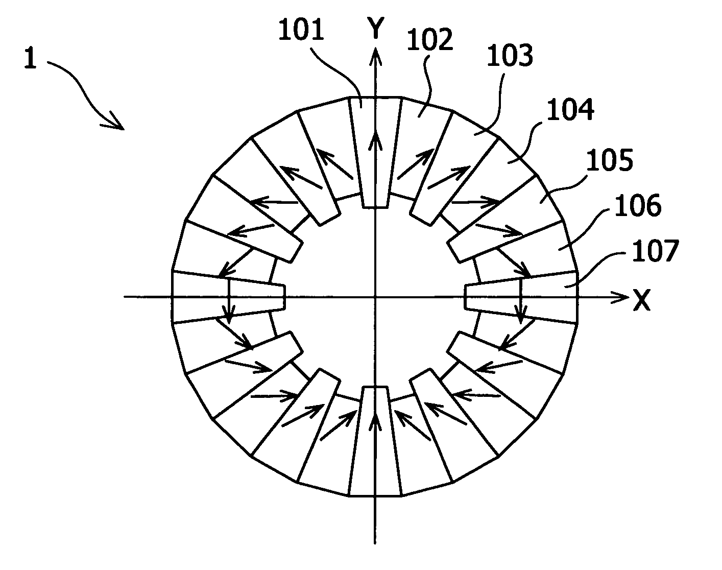
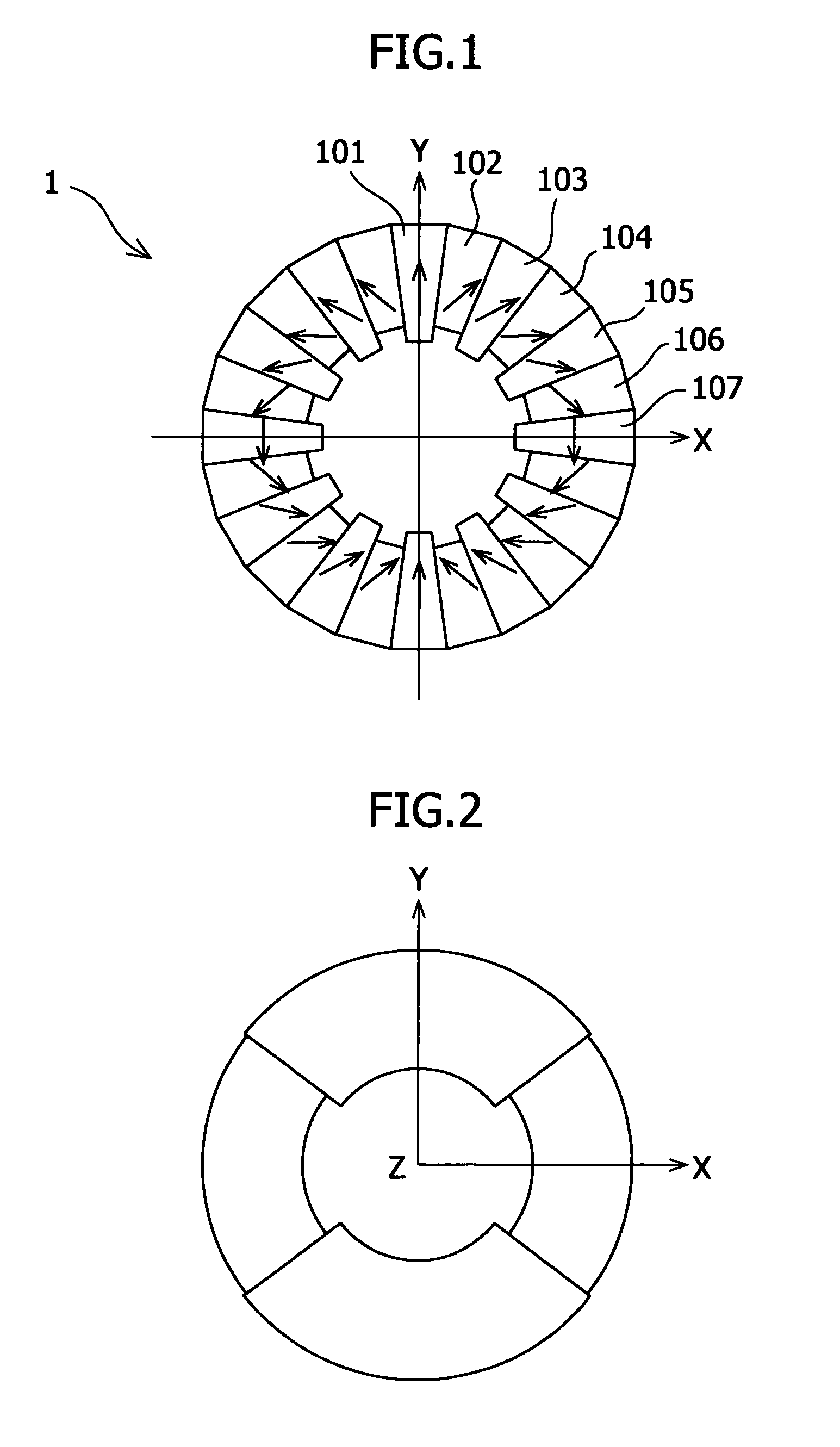
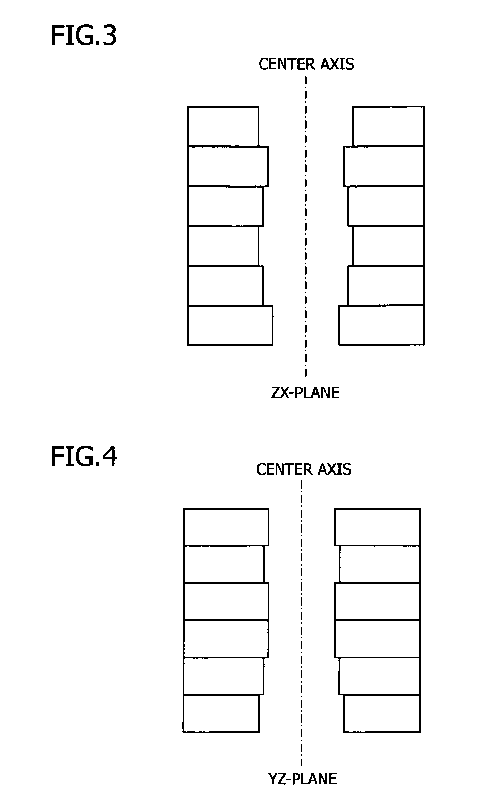
[0048]FIG. 7 is a schematic, cross-sectional view of a dipole ring magnetic field generating apparatus according to the present invention, taking along a plane perpendicular to the center axis. The dipole ring magnetic field generating apparatus according to working example 1 is a dipole ring magnetic field generating apparatus of the shape shown schematically in FIG. 7, and the height of the permanent magnet pieces corresponding to the numbers shown in FIG. 1 are optimized as in Table 1, and it is fabricated based on the results of these calculations. Specifically, in the dipole ring magnetic field generating apparatus 1, 24 substantially trapezoidal permanent magnets 101 to 124 are disposed so as to form a ring shape, and these are encompassed by a perimeter yoke 2 on their outer side. Each permanent magnet piece...


PUM

PropertyMeasurementUnit
magnetic fieldsaaaaaaaaaa
diameteraaaaaaaaaa
diameteraaaaaaaaaa

Abstract

It is an object of the present invention to achieve a magnetic field with high uniformity and low skew angle in a dipole ring magnetic field generating apparatus. There is provided a permanent magnet type magnetic field generating apparatus comprising: a plurality of permanent magnet pieces disposed in a ring shape so that a substantially unidirectional magnetic field is generated in a space within the ring, the permanent magnet pieces having the magnetization direction undergoing one rotation over a half-circumference of the ring, the permanent magnet pieces having substantially the same magnetic strength, and the permanent magnet pieces being disposed so as to form indentations and protrusions toward a center axis of the ring, or having a shape having indentations and protrusions facing the center axis.

Description

BACKGROUND OF THE INVENTION[0001]1. Field of the Invention[0002]The present invention relates to permanent magnet type magnetic field generating apparatuses.[0003]2. Description of Related Art[0004]As will be explained in detail below, generally, a dipole ring magnetic field generating apparatus comprises a plurality of permanent magnets disposed in a ring shape such that the magnetization direction of the permanent magnet pieces undergoes one rotation over a half-circumference of the ring, and generates a substantially unidirectional magnetic field in a space within the ring, and have permanent magnet pieces whose magnetic strength is the same. Such dipole ring magnetic field generating apparatuses are utilized widely as uniform magnetic field generating means, for example, in magnetic resonance imaging (MRI) devices, semiconductor element manufacturing processes and in fundamental research. (See Halbach, K. Design of permanent magnet multipole magnets with oriented rare earth coba...

Claims


Application Information

Patent Timeline
Patent Type & Authority Patents(United States)
IPC IPC(8): H01F7/02A61B5/055G01R33/383
CPCH01F7/0278G01R33/383
Inventor HIGUCHI, DAI
Owner SHIN ETSU CHEM IND CO LTD
Why Eureka
Try Eureka