
Tire monitoring with passive and active modes

Inactive Publication Date: 2010-07-20
AMERICAN VEHICULAR SCI
View PDF25 Cites 64 Cited by
  • Summary
  • Abstract
  • Description
  • Claims
  • Application Information

AI Technical Summary

Problems solved by technology

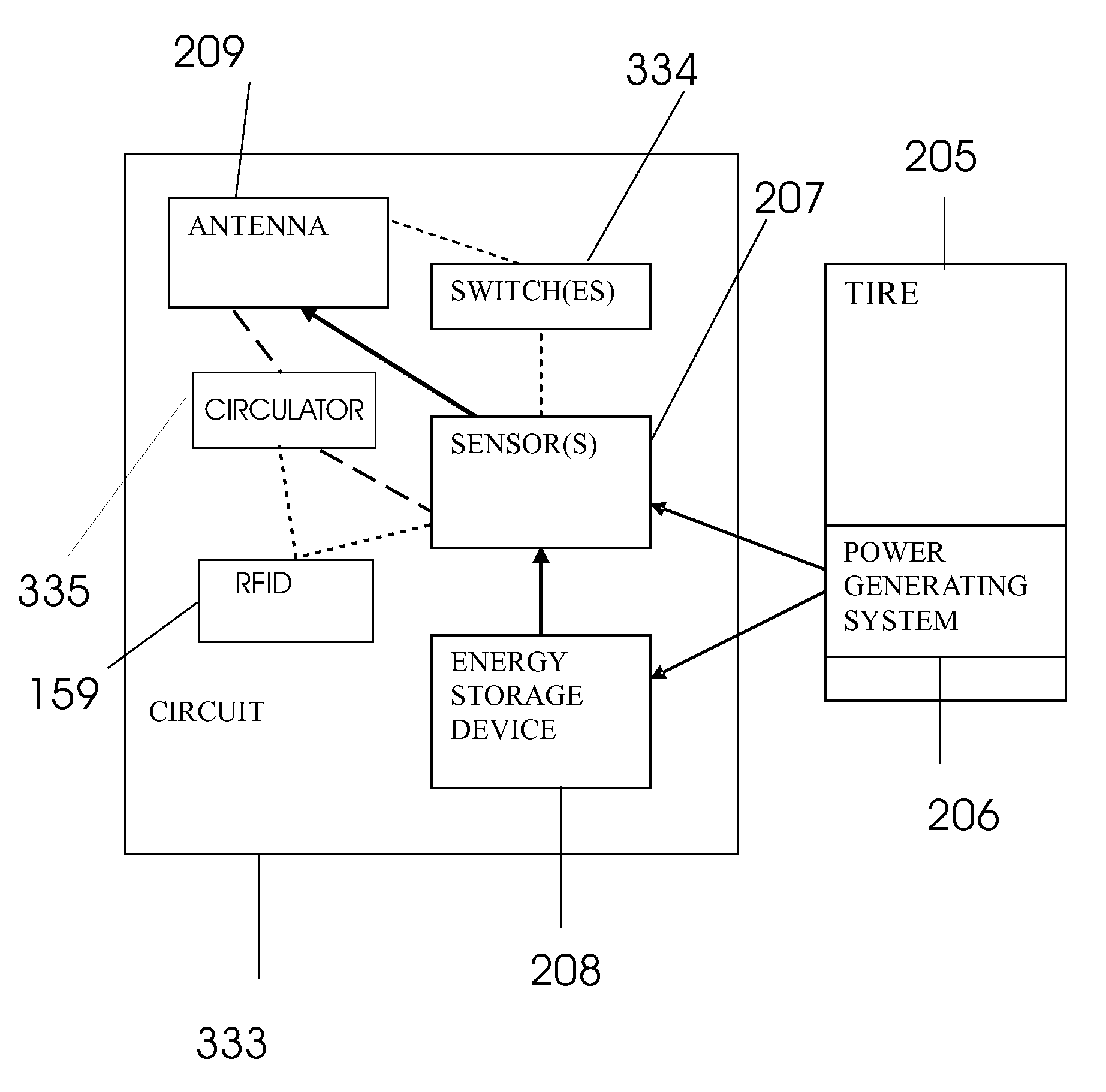
The circuit is operable in an active mode when the substrate moves and the power generating system generates energy or the energy storage device contains energy for powering the circuit and in a passive mode when the substrate is not moving and the energy storage device does not contain sufficient energy to power the circuit.

Method used


Image

  • Tire monitoring with passive and active modes
  • Tire monitoring with passive and active modes
  • Tire monitoring with passive and active modes

Examples


first embodiment

[0571]Referring now to FIGS. 29A and 29B, a valve cap 149 including a tire pressure monitoring system in accordance with the invention is shown generally at 10 in FIG. 29A. A tire 140 has a protruding, substantially cylindrical valve stem 141 which is shown in a partial cutaway view in FIG. 29A. The valve stem 141 comprises a sleeve 142 and a tire valve assembly 144. The sleeve 142 of the valve stem 141 is threaded on both its inner surface and its outer surface. The tire valve assembly 144 is arranged in the sleeve 142 and includes threads on an outer surface which are mated with the threads on the inner surface of the sleeve 142. The valve assembly 144 comprises a valve seat 143 and a valve pin 145 arranged in an aperture in the valve seat 143. The valve assembly 144 is shown in the open condition in FIG. 29A whereby air flows through a passage between the valve seat 143 and the valve pin 145.

[0572]The valve cap 149 includes a substantially cylindrical body 148 and is attached to ...

second embodiment

[0574]a valve cap 10′ in accordance with the invention is shown in FIG. 29B and comprises a SAW strain sensing device 154 that is mounted onto a flexible membrane 152 attached to the body 148 of the valve cap 149 and in a position in which it is exposed to the air in the chamber 151. When the pressure changes in chamber 151, the deflection of the membrane 152 changes thereby changing the strain in the SAW device 154. This changes the path length that the waves must travel which in turn changes the natural frequency of the SAW device or the delay between reception of an interrogating pulse and its retransmission.

[0575]Strain sensor 154 is thus a differential pressure-measuring device. It functions based on the principle that changes in the flexure of the membrane 152 can be correlated to changes in pressure in the chamber 151 and thus, if an initial pressure and flexure are known, the change in pressure can be determined from the change in flexure or strain.

[0576]FIGS. 29A and 29B th...


PUM


Abstract

Movable vehicular assembly including an electricity generating system includes a movable substrate such as a tire, a power generating system arranged on, in connection with or within the substrate and to generate energy from movement of the substrate, and a circuit coupled to the power generating system and including an energy storage device. The circuit is operable in an active mode when the substrate moves and the power generating system generates energy or the energy storage device contains energy for powering the circuit and in a passive mode when the substrate is not moving and the energy storage device does not contain sufficient energy to power the circuit. The circuit receives power to operate in the passive mode from a signal received by the circuit. Components which may be part of the circuit include a surface-acoustic-wave device and a radio-frequency identification device.

Description

CROSS REFERENCE TO RELATED APPLICATIONS[0001]This application[0002]1. a continuation-in-part (CIP) of U.S. patent application Ser. No. 10 / 642,028 filed Aug. 15, 2003, now U.S. Pat. No. 7,253,725, which claims priority under 35 U.S.C. §119(e) of U.S. provisional patent application Ser. No. 60 / 415,862 filed Oct. 3, 2002, now expired;[0003]2. a CIP of U.S. patent application Ser. No. 10 / 931,288 filed Aug. 31, 2004, now U.S. Pat. No. 7,164,117, which is a[0004]A. a CIP of U.S. patent application Ser. No. 10 / 613,453 filed Jul. 3, 2003, now U.S. Pat. No. 6,850,824, which is a continuation of U.S. patent application Ser. No. 10 / 188,673 filed Jul. 3, 2002, now U.S. Pat. No. 6,738,697, which is:[0005]1) a CIP of U.S. patent application Ser. No. 10 / 079,065 filed Feb. 19, 2002, now U.S. Pat. No. 6,662,642, which is:[0006]a) a CIP of U.S. patent application Ser. No. 09 / 765,558 filed Jan. 19, 2001, now U.S. Pat. No. 6,748,797, which claims priority under 35 U.S.C. §119(e) of U.S. provisional pat...

Claims


Application Information

Patent Timeline
Patent Type & Authority Patents(United States)
IPC IPC(8): B60C23/00
CPCB60C23/0408B60C23/0433
Inventor BREED, DAVID S.DUVALL, WILBUR E.JOHNSON, WENDELL C.
Owner AMERICAN VEHICULAR SCI
Learn More