Liquid crystal device and electronic apparatus

a liquid crystal device and electronic equipment technology, applied in the direction of instruments, substation equipment, optics, etc., can solve the problem that users of the devices generally dislike other people viewing images displayed on the devices, and achieve the effect of lowering the contrast of images

Active Publication Date: 2010-07-20
JAPAN DISPLAY WEST
View PDF8 Cites 2 Cited by
  • Summary
  • Abstract
  • Description
  • Claims
  • Application Information

AI Technical Summary

Benefits of technology

[0011]An advantage of some aspects of the invention is that it provides a liquid crystal device that has both a wide viewing angle display mode and a narrow viewing angle display mode and is capable of lowering a contrast of an image when viewed from a specific direction in the narrow viewing angle display mode and an electronic apparatus to which the same is applied.
[0014]Moreover, the alignment direction (direction of a liquid crystal alignment axis) of the liquid crystal molecules of the viewing angle control panel is substantially parallel or perpendicular to the transmission axis of the one polarizing plate. Accordingly, a range of the viewing angle of a polar angle direction substantially perpendicular to the alignment direction of the liquid crystal molecules of the viewing angle control panel can be limited, and specifically, the contrast of the image can be lowered. For example, the viewing angle control panel of the liquid crystal device can be disposed so that the alignment direction of the liquid crystal molecules of the viewing angle control panel is a vertical direction with respect to an image surface when the images are viewed from a front side. Accordingly, the viewing angle of a horizontal direction (direction of 3 o'clock to 9 o'clock direction in a clockwise direction) can be limited. That is, the contrast of the images can be lowered. As a result, it is possible to prevent other people from viewing the image except for a user.
[0021]According to another aspect of the invention, there is provided an electronic apparatus including the above-described liquid crystal device as a display unit. According to such a configuration, for example, it is possible to configure the electronic apparatus capable of having both wide viewing angle display mode and narrow viewing angle display mode and lowering the contrast of the image when viewed from a specific direction in the narrow viewing angle display mode.

Problems solved by technology

Alternatively, when the display devices are used outside or in public places, users of the devices generally dislike other people viewing images displayed on the devices.

Method used


Image

  • Liquid crystal device and electronic apparatus
  • Liquid crystal device and electronic apparatus
  • Liquid crystal device and electronic apparatus

Examples


first embodiment

Configuration of Liquid Crystal Device

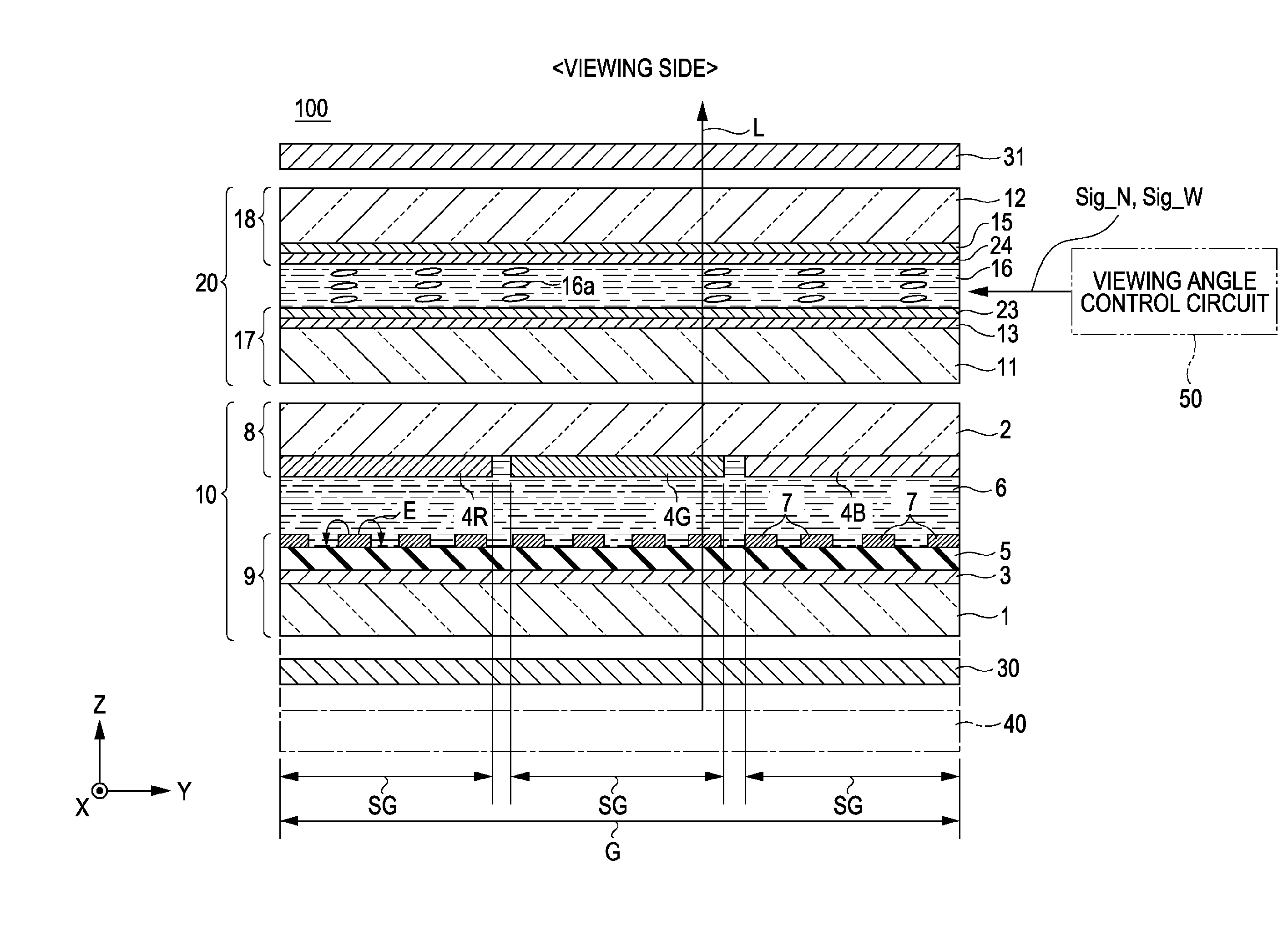
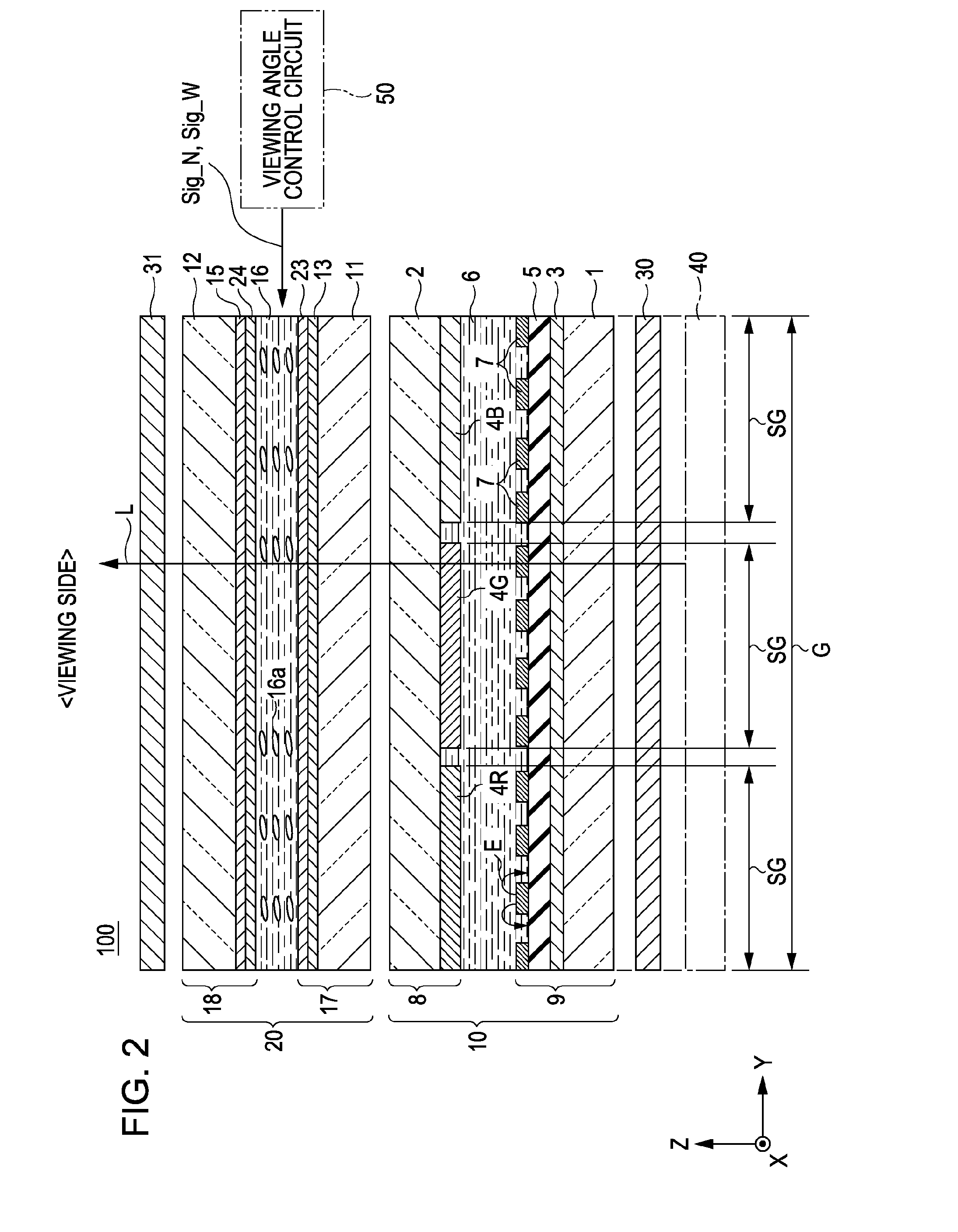
[0043]FIG. 2 is a sectional view schematically illustrating a configuration of a liquid crystal device 100 according to a first embodiment of the invention.

[0044]In the liquid crystal device 100 according to the first embodiment, a second polarizing plate 31, a viewing angle control panel 20, a display panel 10, a first polarizing plate 30, and an illuminating device 40 are subsequently arranged. Moreover, the liquid crystal device 100 includes a viewing angle control circuit 50 for controlling the viewing angle control panel 20.

[0045]The second polarizing plate 31, which carries out a function of generating linearly polarized light, includes a transmission axis 31dr (see FIGS. 3A, 3B, and 3C) for transmitting light vibration and an absorption axis for absorbing the light vibration in a direction perpendicular to the transmission axis 31dr. Similarly, the first polarizing plate 30 also includes a transmission axis 30dr (see FIGS. 3A, 3B, and 3C)...

second embodiment

[0066]FIG. 7 is a schematically sectional view illustrating a liquid crystal device 200 according to a second embodiment of the invention.

[0067]When the second embodiment is compared to the first embodiment, a configuration of a display panel is different and others are the same. That is, the display panel 10 according to the first embodiment is of the fringe field switching (FFS) mode of the transverse electric field mode, but a display panel 11 according to the second embodiment is different in that the display panel 11 is a display panel of a circularly polarized light type emitting circularly polarized light toward the viewing angle control panel 20 and a display panel of a vertical alignment mode. In addition, the liquid crystal device 200 according to the second embodiment is different from that according to the first embodiment in that a phase difference film 32 for changing the circularly polarized light emitted from the display panel 11 to a viewing side to linearly polariz...

third embodiment

[0078]FIG. 9 is a schematically sectional view illustrating a liquid crystal device 300 according to a third embodiment of the invention.

[0079]When the third embodiment is compared to the first embodiment, a liquid crystal alignment state and a method of controlling viewing angles of a viewing angle control circuit in a viewing angle control panel are different and others are the same. Hereinafter, the same reference numerals are given to the same constituents as those according to the first embodiment and the detailed description will be omitted.

[0080]A viewing angle control panel 21 according to the third embodiment includes a first substrate 17x and a second substrate 18x with a liquid crystal layer 16x interposed therebetween. The liquid crystal layer 16x formed of a liquid crystal material in which dielectric anisotropy is negative is of a hybrid arrayed nematic (HAN) type in which hybrid alignment is formed. In this case, the “hybrid alignment” means an alignment state where a...


PUM

PropertyMeasurementUnit
voltageaaaaaaaaaa
polar anglesaaaaaaaaaa
intersecting angleaaaaaaaaaa

Abstract

A liquid crystal device includes a pair of polarizing plates having a transmission axis; a display panel being disposed between the pair of polarizing plates and having a function of displaying an image; and a viewing angle control panel having a liquid crystal layer that is disposed at a position adjacent to one of the pair of polarizing plates between the pair of polarizing plates with liquid crystal molecules aligned in a predetermined direction and controlling a viewing angle of a display on the display panel, wherein the alignment direction of the liquid crystal molecules of the viewing angle control panel is substantially parallel or perpendicular to a transmission axis of the one polarizing plate.

Description

[0001]The entire disclosure of Japanese Patent Application No. 2006-293626, filed Oct. 30, 2006 is expressly incorporated by reference herein.BACKGROUND[0002]1. Technical Field[0003]The present invention relates to a liquid crystal device and an electronic apparatus capable of switching between both wide viewing angle and narrow viewing angle display modes.[0004]2. Related Art[0005]Recently, it is required that display devices such as laptop computers and cellular phones have wide viewing angle characteristics so as to be normally viewed from any direction. Alternatively, when the display devices are used outside or in public places, users of the devices generally dislike other people viewing images displayed on the devices. In this case, narrow viewing angle characteristics is required. For this reason, there have been suggested various display devices capable of switching between a wide viewing angle state and a narrow viewing angle state (for example, see JP-A-2006-64882, JP-A-20...

Claims


Application Information

Patent Timeline
Patent Type & Authority Patents(United States)
IPC IPC(8): G02F1/1337
CPCG02F1/1323G02F1/1347G02F2001/134372H04M1/0266G02F1/134372
Inventor MATSUSHIMA, TOSHIHARU
Owner JAPAN DISPLAY WEST
Why Eureka
Try Eureka