
Torque-filling power transfer assembly for a manual transmission

a transmission assembly and torque filling technology, applied in differential gearings, toothed gearings, fluid gearings, etc., can solve the problems of significant heat generation of the clutch, undesirable lurching or other sensations in the vehicle, and interruption of torque during the gear shift. achieve the effect of avoiding torque gaps

Inactive Publication Date: 2010-07-27
SCHAEFFLER TECH AG & CO KG
View PDF6 Cites 2 Cited by
  • Summary
  • Abstract
  • Description
  • Claims
  • Application Information

AI Technical Summary

Benefits of technology

[0013]It is another object of the present invention to provide a means of avoiding torque gaps during a gear shift in a manual transmission.

Problems solved by technology

That is, torque interruptions occur during the gear shift.
Unfortunately, these interruptions can result in undesirable lurching or other sensations in the vehicle.
Unfortunately, the operation of the clutches generates significant amounts of heat that may require extensive modification of cooling systems for the drive train in the vehicle.

Method used


Image

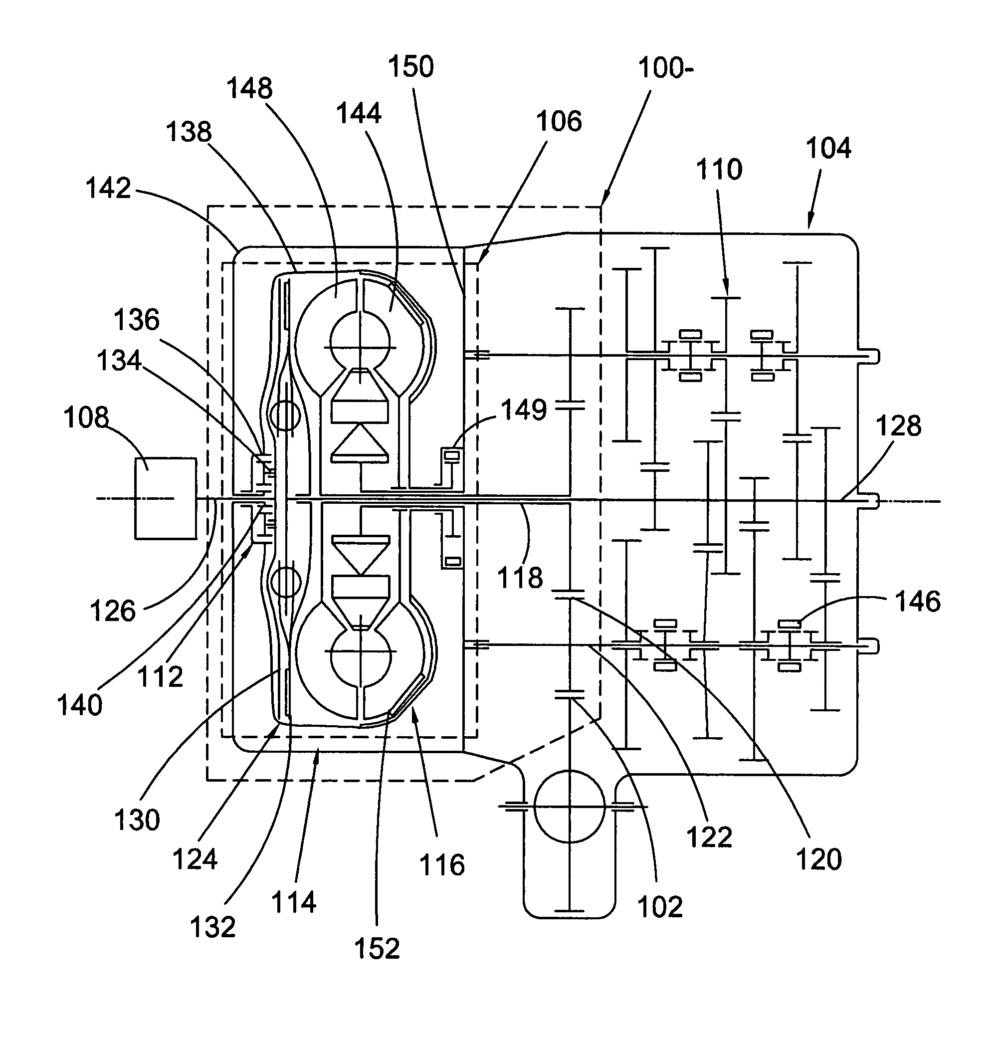
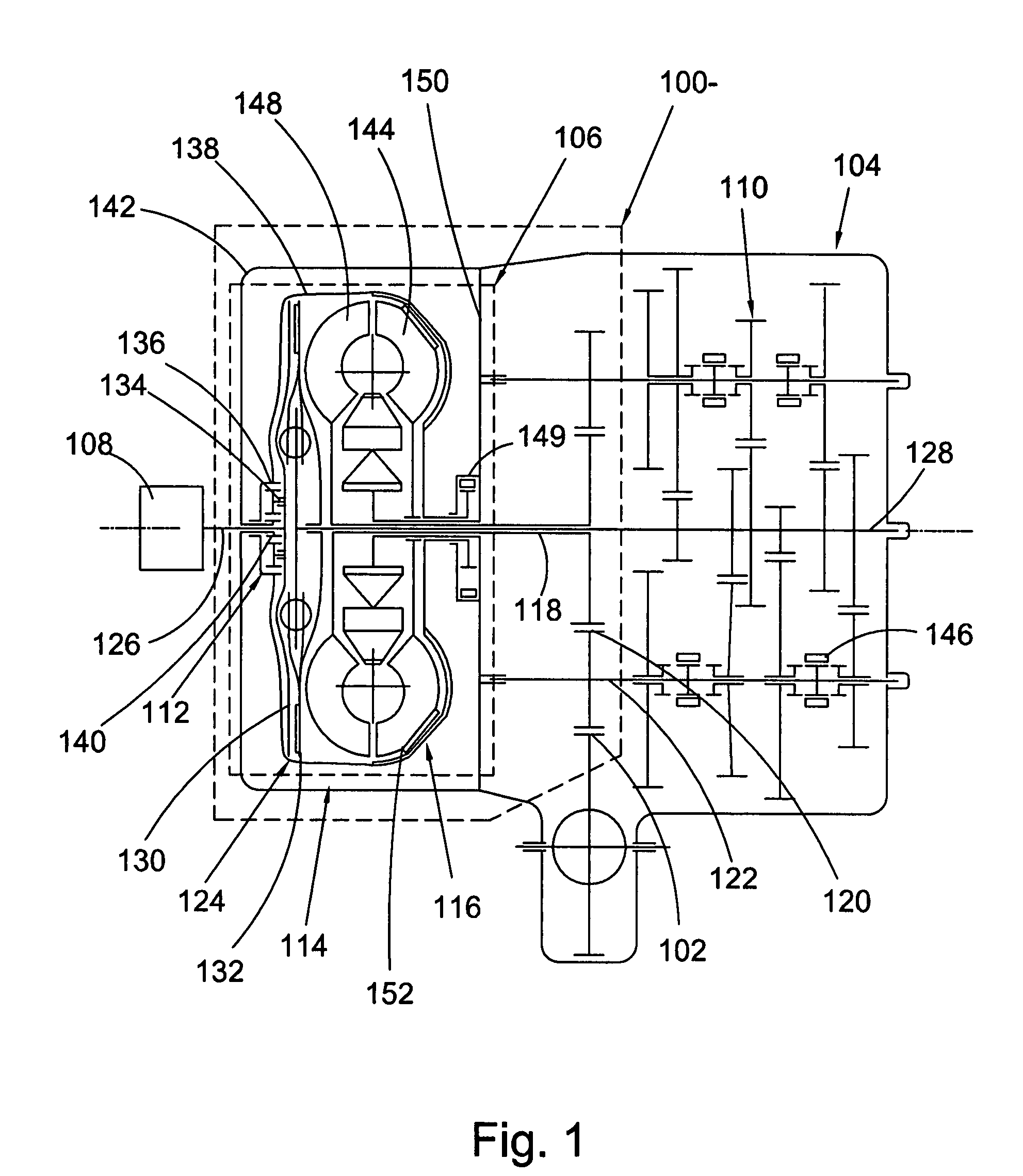
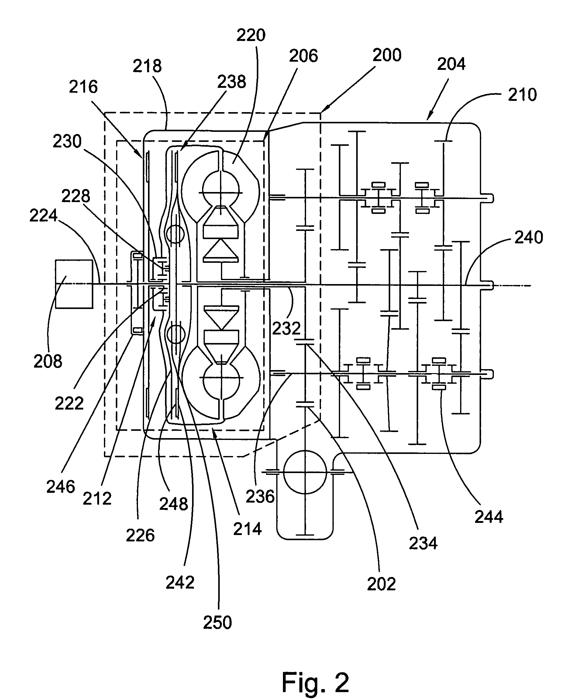
  • Torque-filling power transfer assembly for a manual transmission
  • Torque-filling power transfer assembly for a manual transmission
  • Torque-filling power transfer assembly for a manual transmission

Examples


Embodiment Construction

[0020]At the outset, it should be appreciated that like drawing numbers on different drawing views identify identical, or functionally similar, structural elements of the invention. While the present invention is described with respect to what is presently considered to be the preferred aspects, it is to be understood that the invention as claimed is not limited to the disclosed aspects.

[0021]Furthermore, it is understood that this invention is not limited to the particular methodology, materials and modifications described and as such may, of course, vary. It is also understood that the terminology used herein is for the purpose of describing particular aspects only, and is not intended to limit the scope of the present invention, which is limited only by the appended claims.

[0022]Unless defined otherwise, all technical and scientific terms used herein have the same meaning as commonly understood to one of ordinary skill in the art to which this invention, belongs. Although any met...


PUM


Abstract

The present invention broadly comprises a power transmitting assembly for a vehicle, including a transmission power output for a manual transmission in the vehicle and a torque-filling element. The torque-filling element is arranged for connection to an engine in the vehicle, is connected to the transmission power output and is arranged to modify engine torque from the engine and to provide the modified engine torque to the transmission power output during a shift to a gear in the manual transmission. The torque-filling element includes a hydrodynamic torque-transmitting device, a rotation adjustment element to modify rotational speed associated with the engine, and a coupling element to interface the engine torque with torque on the transmission power output. In some aspects, the rotation adjustment element is arranged for connection to the engine. In some aspects, the coupling element is arranged for connection to the engine.

Description

CROSS-REFERENCE TO RELATED APPLICATIONS[0001]This application claims the benefit under 35 U.S.C. §119(e) of U.S. Provisional Application No. 60 / 796,481 filed May 1, 2006.FIELD OF THE INVENTION[0002]The invention relates to improvements in apparatus for transmitting force between a rotary driving unit (such as the engine of a motor vehicle) and a rotary driven unit (such as the variable-speed transmission in the motor vehicle). In particular, the invention relates to a power transmitting assembly to provide fill-in torque during a gear shift in a manual transmission. Specifically, the assembly uses a hydrodynamic component to interface engine and transmission torques.BACKGROUND OF THE INVENTION[0003]During the typical gear shifting operation in a manual transmission, the transmission is at least partially disconnected from the engine in the vehicle providing torque to the transmission. That is, torque interruptions occur during the gear shift. Unfortunately, these interruptions can r...

Claims


Application Information

Patent Timeline
Patent Type & Authority Patents(United States)
IPC IPC(8): F16H47/06
CPCF16H3/006F16H37/06F16H47/06F16H3/08F16H47/085Y10T74/19033F16H2037/0873F16H2045/0268F16H2061/0425F16H2061/0429F16H2200/0052F16H61/04
Inventor MAUCHER, EDMUNDHEMPHILL, JEFFREY
Owner SCHAEFFLER TECH AG & CO KG
Learn More