Stator for rotary electric machines

a technology of rotating electric machines and rotors, which is applied in the direction of instruments, horology, magnetic circuit shapes/forms/construction, etc., can solve the problems of reducing the volume of the rotor, the nozzle movement becoming complicated, and the connecting wire becoming rather long, so as to reduce the dimension, simplify the arrangement or formation of the connecting wire, and compact in size

Active Publication Date: 2010-07-27
SANYO DENKI CO LTD
View PDF30 Cites 2 Cited by
  • Summary
  • Abstract
  • Description
  • Claims
  • Application Information

AI Technical Summary

Benefits of technology

[0007]Accordingly, an object of the present invention is to provide a stator for rotary electric machines wherein a volume occupied by winding portions may be increased and a connecting wire may readily be prevented from coming off.
[0008]Another object of the present invention is to provide a stator for rotary electric machines, wherein a circuit substrate is supported at one end of a slot insulator and a distance between the circuit substrate and a stator core may be reduced.

Problems solved by technology

As a result, in the conventional arrangement, there is a limitation in increasing a volume occupied by the winding portions in the slot.
As a result, there are some problems that when disposing the wiring wire, the movement of the nozzle becomes intricate, and the connecting wire becomes rather long.

Method used


Image

  • Stator for rotary electric machines
  • Stator for rotary electric machines
  • Stator for rotary electric machines

Examples


Embodiment Construction

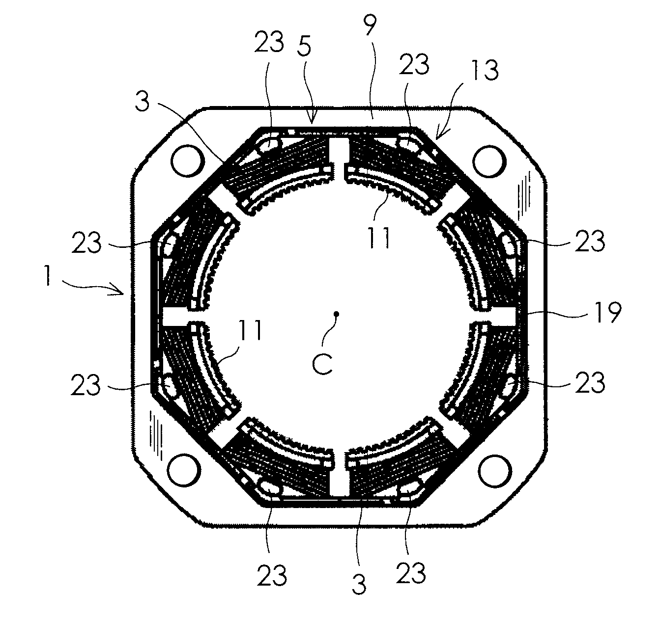
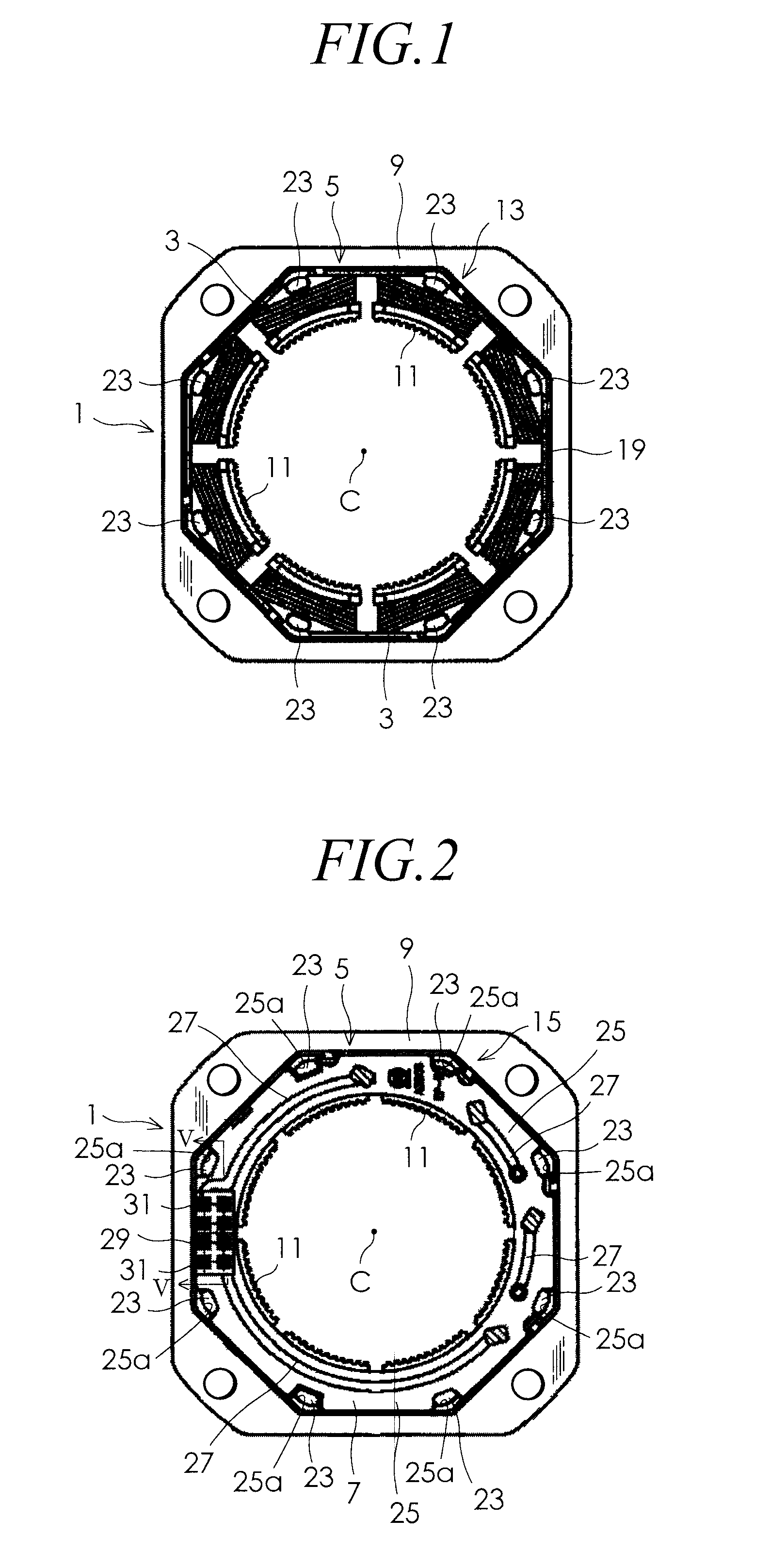
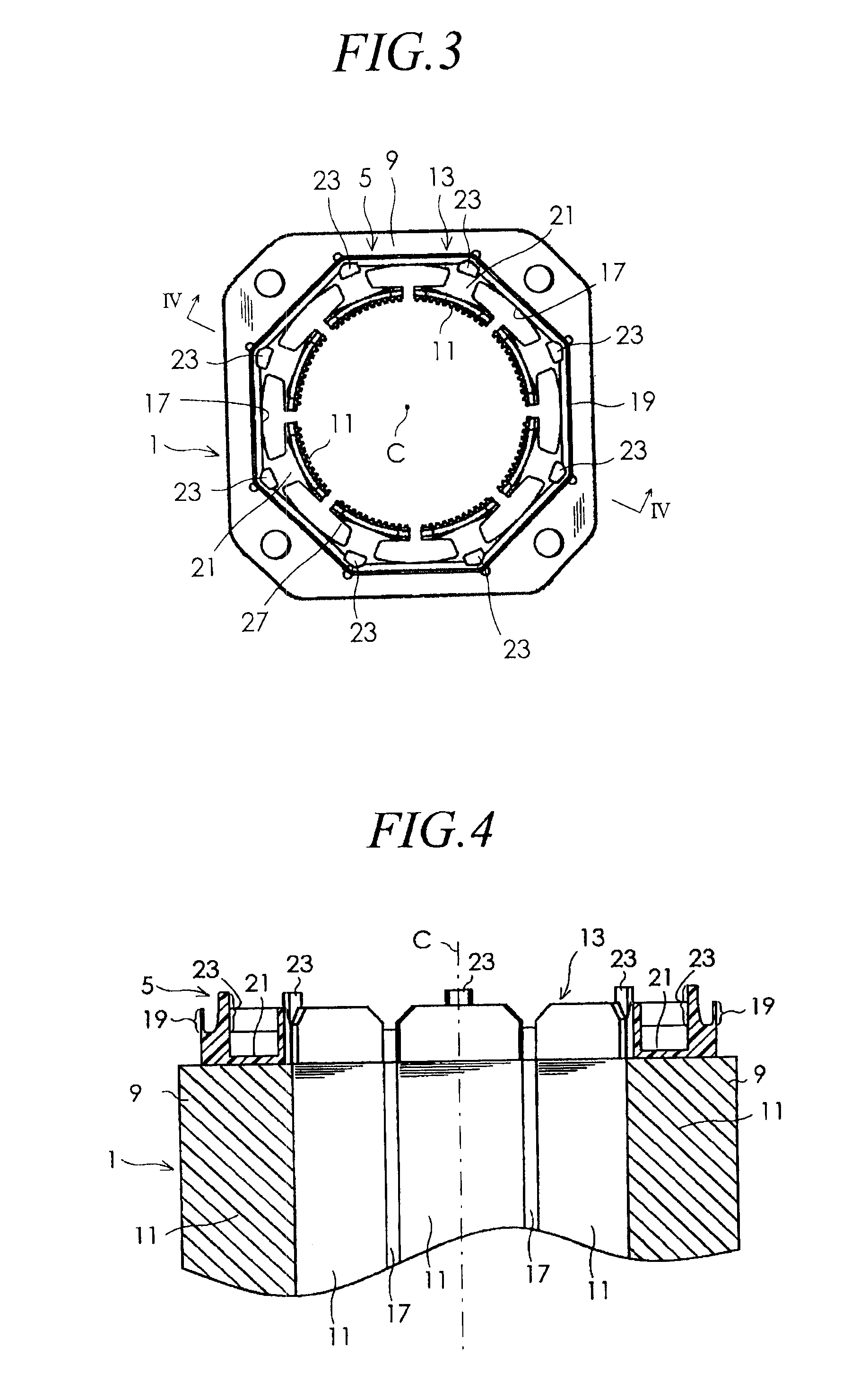
[0024]An embodiment of the present invention will now be described in detail with reference to the accompanying drawings. FIGS. 1 and 2 are respectively a plan view and a back view of a stator for rotary electric machines of one embodiment of the present invention. FIG. 3 is an illustration showing the stator of FIG. 1 wherein an after-mentioned winding portion 3 is omitted. FIG. 4 is a sectional view taken along line IV-IV of FIG. 3. As shown in each figure, the stator for rotary electric machines of the present embodiment comprises a stator core 1, eight winding portions 3, a slot insulators 5, and a circuit substrates 7. The stator core 1 includes an annular yoke 9 and eight magnetic pole sections 11. The eight magnetic pole sections 11 are disposed integrally with the annular yoke 9 on an inner circumferential portion of the annular yoke 9, at intervals in a circumferential direction of the annular yoke 9, and protruding toward a centerline C of the annular yoke 9. The stator co...


PUM


Abstract

A stator for rotary electric machines is provided, in which a volume occupied by winding portions may be increased and a connecting wire may readily be engaged to prevent from coming off. A plurality of connecting wire engaging hooks 23, with which the connecting wire extending from the winding portion is engaged, are respectively disposed in the vicinity of border portions between a plurality of magnetic pole sections 11 and a yoke 9, corresponding to the magnetic pole sections 11. A mounting location of a connector 29 on a circuit substrate 7 is determined so that all of ends of a plurality of terminal conductors of the connector may be located between adjoining two of the connecting wire engaging hooks 23. With this arrangement, all of the ends 31a of the plurality of terminal conductors 31 may be disposed between adjoining two of a plurality of the winding portions 3, and be spaced from the winding portions 3.

Description

BACKGROUND OF THE INVENTION[0001]1. Field of the Invention[0002]The present invention relates to a stator for rotary electric machines.[0003]2. Description of the Related Art[0004]FIG. 13 of Japanese Patent Publication No. 11-206057 shows a stator for rotary electric machines comprising a stator core which includes an annular yoke and a plurality of magnetic pole sections protruding from the annular yoke toward a centerline of the yoke, a plurality of winding portions formed of a winding conductor wound around the magnetic pole sections of the stator core, and a slot insulator which is made of an insulating resin and mounted on the stator core in order to provide electrical insulation between the stator core and the winding portions. The slot insulator includes a plurality of connecting wire engaging hooks which are located at and integrally formed with one of ends thereof, and disposed at certain intervals in a circumferential direction thereof. A connecting wire, which is formed o...

Claims


Application Information

Patent Timeline
Patent Type & Authority Patents(United States)
IPC IPC(8): H02K11/00
CPCH02K3/34H02K5/225H02K3/50H02K3/38H02K2203/03H02K11/0073H02K11/33H02K1/16
Inventor OOHASHI, MASAAKINAKATAKE, KOUJIYODA, YASUSHI
Owner SANYO DENKI CO LTD
Why Eureka
Try Eureka