Door, deep draw molded door facing, and methods of forming door and facing

a deep draw molding and door facing technology, applied in the field of wood composite panels, can solve the problems of surface cracks or defects, increase manufacturing costs, and use of cores, and achieve satisfactory stretch factor and satisfactory stretch factor

a deep draw molding and door facing technology, applied in the field of wood composite panels, can solve the problems of surface cracks or defects, increase manufacturing costs, and use of cores, and achieve satisfactory stretch factor and satisfactory stretch factor

US7765768B2Inactive Publication Date: 2010-08-03MASONITE CORP

Image

  • Door, deep draw molded door facing, and methods of forming door and facing
  • Door, deep draw molded door facing, and methods of forming door and facing
  • Door, deep draw molded door facing, and methods of forming door and facing

Examples


Embodiment Construction

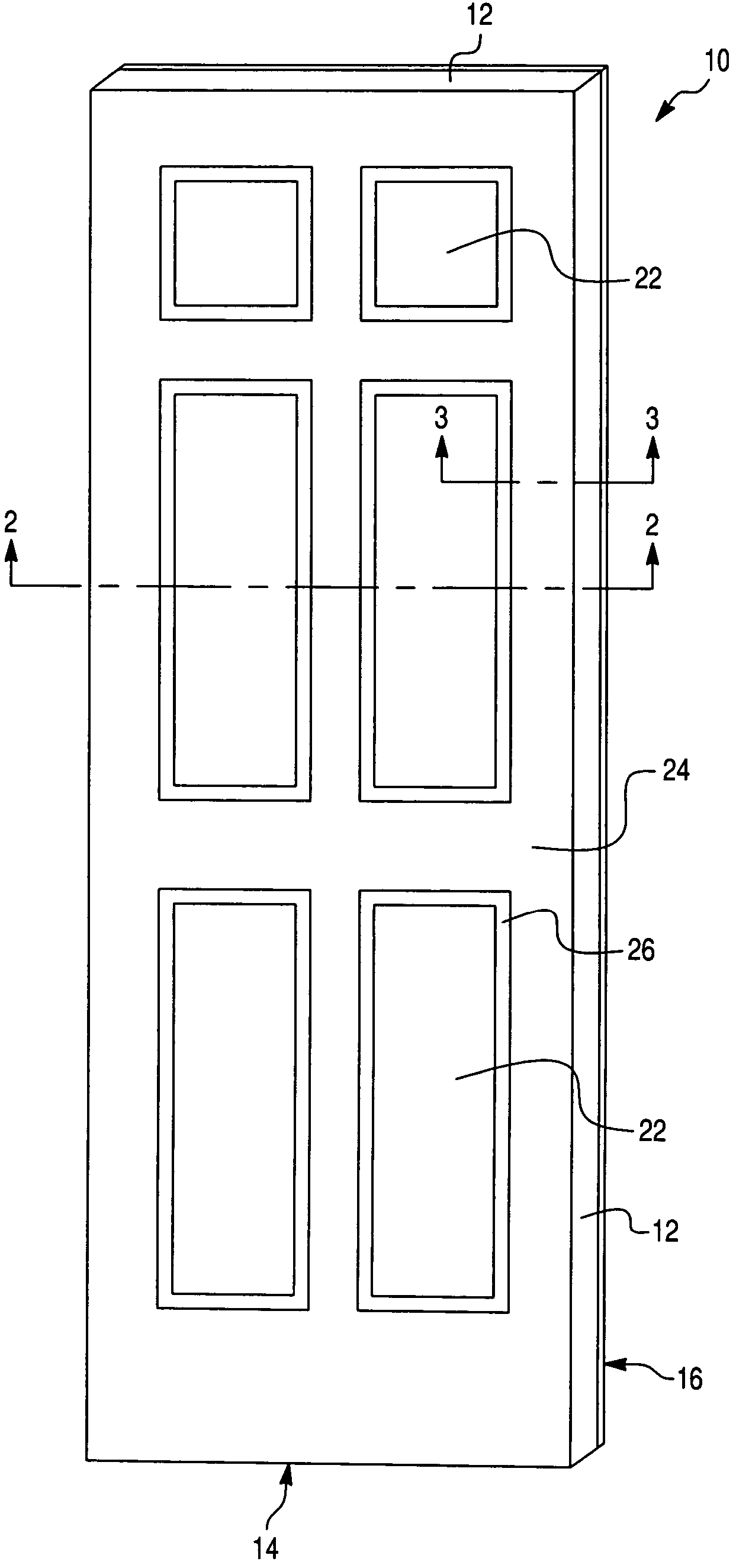
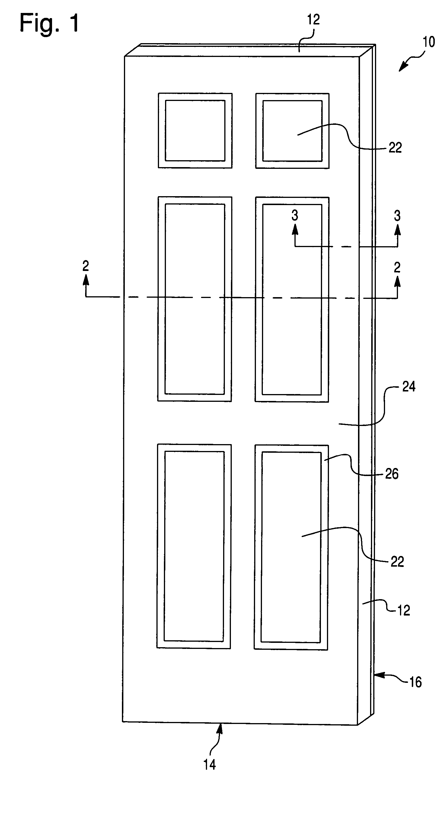
[0020]As best shown in FIGS. 1 and 2, a coreless door 10 comprises a peripheral frame 12, and first and second wood composite door facings 14, 16. Each facing 14, 16 includes an exteriorly disposed first surface 18, and an interiorly disposed second surface 20 secured to opposing sides of frame 12. First and second facings 14, 16 each include one or more panel portions 22 and a major planar portion 24. A contoured portion 26 surrounds each panel portion 22, and is intermediate and integral with major planar portion 24 and panel portion 22. First and second facings 14, 16 may have identical configurations, as best shown in FIG. 2. Contoured portions 26 and panel portions 22 are aligned when facings 14, 16 are secured to frame 12.

[0021]As best shown in FIG. 3, contoured portions 26 include first and second angled areas 28, 30, which extend inwardly relative to exteriorly disposed surface 18, and base 32. Angled areas 28, 30 extend inwardly a sufficient depth to allow interiorly dispos...


PUM

PropertyMeasurementUnit
vector angleaaaaaaaaaa
thicknessaaaaaaaaaa
vector angleaaaaaaaaaa

Abstract

The present invention relates to a wood composite panel having a major planar portion, at least one panel portion, and an inwardly extending contoured portion surrounding the panel portion and interconnecting the major planar portion and the panel portion. The contoured portion defines an inter-relationship between a vector angle and a deep draw depth that achieve a satisfactory stretch factor. The present invention also relates to a door having the disclosed wood composite door facings, and methods of forming the facing and door.

Description

CROSS REFERENCE TO RELATED APPLICATIONS AND CLAIM TO PRIORITY[0001]The present application claims the benefit of priority of provisional application Ser. No. 60 / 536,846, filed Jan. 16, 2004, and provisional application Ser. No. 60 / 536,845, also filed Jan. 16, 2004, the disclosures of which are incorporated herein by reference and to which priority is claimed under 35 U.S.C. §119.FIELD OF THE INVENTION[0002]The present invention relates to a wood composite panel, such as a door facing, having a major planar portion, at least one panel portion, and an extending contoured portion surrounding the panel portion and interconnecting the major planar portion and the panel portion. The contoured portion has a vector angle and a draw depth that achieve a satisfactory stretch factor. The present invention also relates to a door having the disclosed wood composite door facings, and methods of forming the facing and door.BACKGROUND OF THE INVENTION[0003]Hollow core doors simulating natural, soli...

Claims


Application Information

Patent Timeline
03 Aug 2010
Publication
US7765768B2
IPC
B44F7/00; E06B3/70; E04C2/54; B32B5/12; B27N5/00; E06B3/74
CPC
B27N5/00; E06B3/7001; E06B3/74; E06B3/7017; Y10T428/24066; E06B2003/7019; Y10T156/1002; B27N3/10
Inventors
LIANG, BEI HONG; WALSH, JASON M.