
Tire and tire producing method

a technology of tire and extruder, which is applied in the field of tires, can solve the problems of deteriorating tire uniformity, hardly discharged static electricity generated in a vehicle through the tire toward the road surface, and the orifice set in the extruder once cannot be easily exchanged with another orifice, so as to achieve the effect of improving tire uniformity and low cos

Inactive Publication Date: 2010-08-03
BRIDGESTONE CORP
View PDF17 Cites 2 Cited by
  • Summary
  • Abstract
  • Description
  • Claims
  • Application Information

AI Technical Summary

Benefits of technology

[0007]The invention is made considering the above problems and is to provide a tire in which the tire uniformity is improved in the tire comprising a tread layer consisting of a tread rubber and an electrically conductive band arranged in a widthwise middle portion thereof and the production is possible in a multi-size mixed production system and the widthwise thickness of the electrically conductive band can be controlled at minimum and a conductive path from a belt to a treading face can be surely formed in a low cost as well as a method of producing such a tire.

Problems solved by technology

However, a tread rubber compounded with a great amount of silica becomes higher in the value of electric resistance, and hence there is caused a problem that static electricity generated in a vehicle hardly discharge through the tire toward a road surface.
However, these proposals have the following problems.
As to the first proposal, the tread rubber is naturally formed by winding an elongate rubber extruded through an orifice corresponding to a shape of a tire product on a full periphery of a tire once, so that the thus formed tread rubber has a joint portion at one place of the periphery, which is a cause of deteriorating the tire uniformity.
Also, the formation of such a tread rubber needs a large-size extruder but also the orifice set in the extruder once can not be easily exchanged with another new orifice, so that there is a drawback that this proposal can not be applied to an efficient system of mixedly producing tires of various sizes while reducing intermediate stock.
However, the electrically conductive band of the second proposal has a problem that the band has a structure of winding and laminating a continuous uncured conductive rubber ribbon and the thickness becomes considerably thicker than the naturally required thickness.
In the first and second proposals, however, the electrically conductive band is exposed to the adjacent face as only a narrow-width line, and in this case, a portion not exposing to the adjacent face may be caused due to the scattering in the production.
Also, when two of the tread layers having the above structure are laminated, the exposing portions of the electrically conductive bands are not matched with each other in the widthwise direction or it is difficult to ensure the electric conduction among these layers.
If it is intended to control the scattering in the production for preventing this drawback, a production equipment of a high precision is required and hence there is caused a problem rendering a significant cost-up.

Method used


Image

  • Tire and tire producing method
  • Tire and tire producing method
  • Tire and tire producing method

Examples


Embodiment Construction

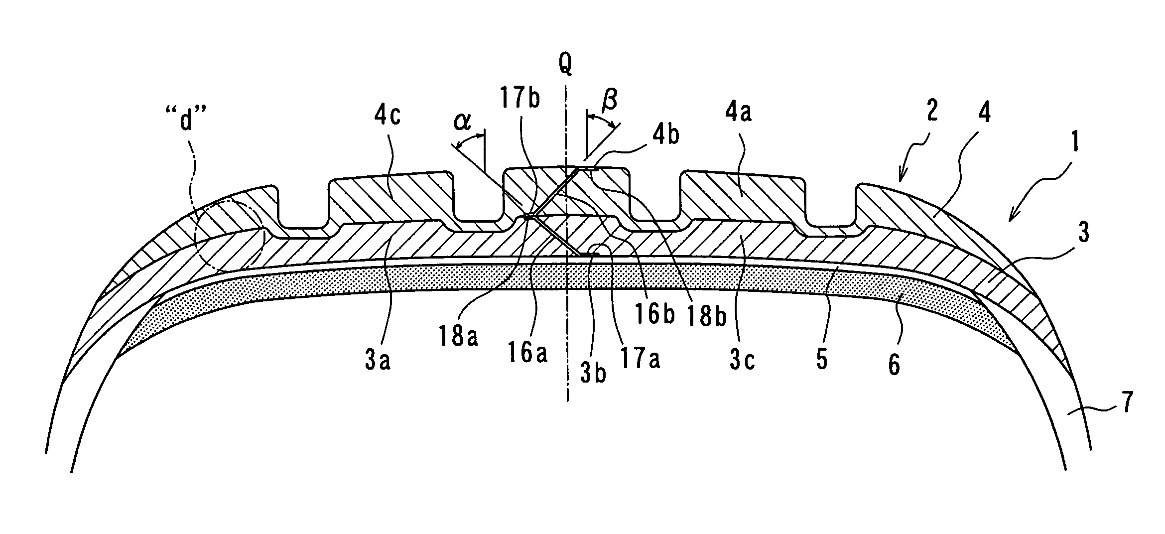
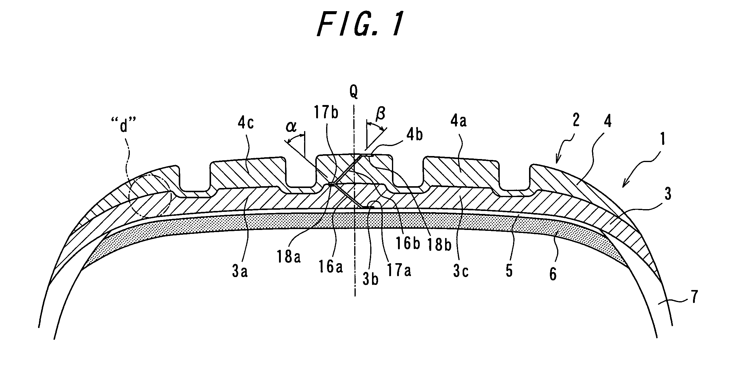
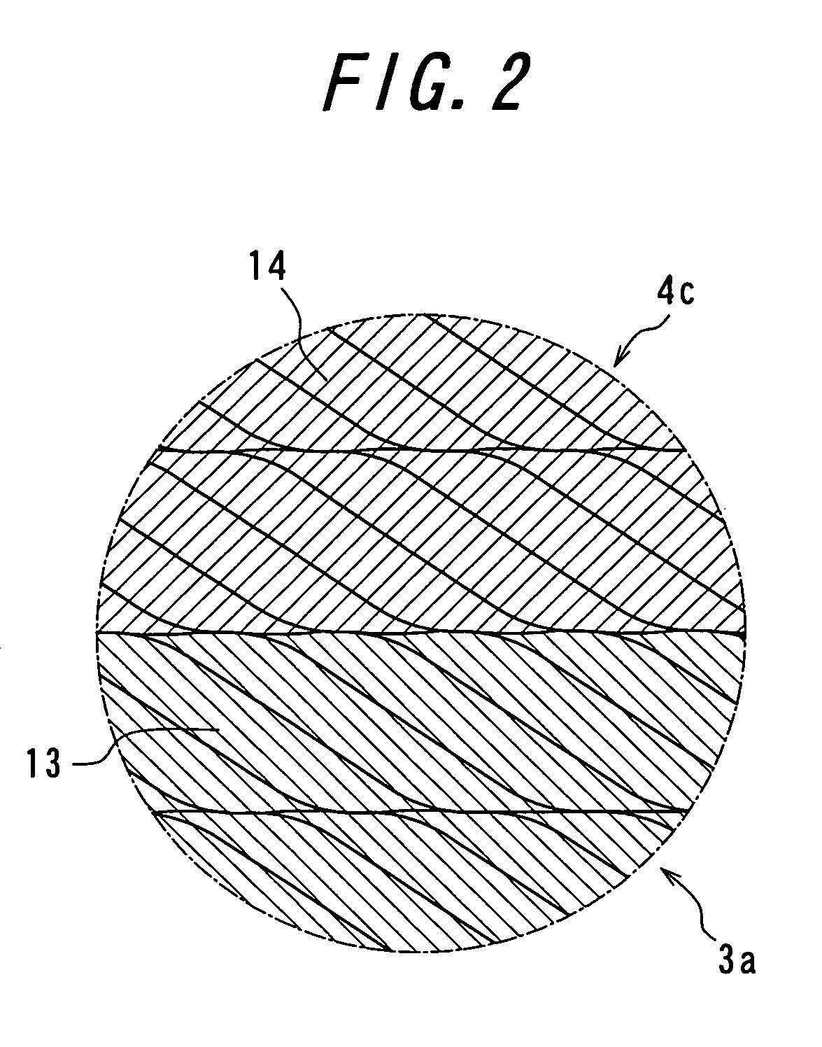
[0038]An embodiment of the invention will be described with reference to FIGS. 1-6. FIG. 1 is a meridianal section view showing a tread portion of a tire according to an embodiment of the invention, and FIG. 2 is a section view showing a detail of a portion “d” in FIG. 1. The tire 1 comprises a belt 6, a tread under cushion 5 arranged on an outer periphery 9 of the belt 6 and sidewall portions 7 disposed on both sides thereof in the widthwise direction, in which a base tread layer 3 and a cap tread layer 4 disposed outside thereof are arranged outward in the radial direction thereof as a tread layer constituting a tread 2. The base tread layer 3 comprises a first tread rubber portion 3a and a second tread rubber portion 3c having a low electric conduction, and an electrically conductive band 3b having a high electric conduction and arranged in a middle portion of the tread rubber in a widthwise direction of the tire, in which each of the first and second tread rubber portions 3a, 3c...


PUM

PropertyMeasurementUnit
inclination angleaaaaaaaaaa
widthaaaaaaaaaa

Abstract

A tire comprising a tread layer comprised of a tread rubber and an electrically conductive band arranged in a widthwise middle portion thereof, and a method of producing the tire, wherein the tread rubber is made of a low-conductive continuous rubber ribbon circumferentially wound plural times, and the electrically conductive band is made of a high-conductive thin annular rubber sheet. Also, the electrically conductive band is arranged so as to extend in the widthwise region ranging from a part of the top face of the first tread rubber portion to a part of the bottom face of the second tread rubber portion, whereby the tire uniformity is improved and the production is possible in a multi-size mixed production system and the conductive path from the belt to the treading face can be surely formed at a low cost.

Description

TECHNICAL FIELD[0001]This invention relates to a tire capable of sufficiently discharging static electricity generated in a vehicle toward a road surface while reducing the rolling resistance of the tire and a method of producing the same.BACKGROUND ART[0002]In order to reduce the rolling resistance of the tire, a greater part of carbon black compounded in a tread rubber tends to be positively replaced with silica having a low hysteresis characteristic. However, a tread rubber compounded with a great amount of silica becomes higher in the value of electric resistance, and hence there is caused a problem that static electricity generated in a vehicle hardly discharge through the tire toward a road surface.[0003]For the purpose of ensuring the discharge property of the tread rubber is proposed a tire wherein a tread is constructed with at least one tread layer comprising a tread rubber having a low electric conduction and an electrically conductive band arranged in a widthwise middle ...

Claims


Application Information

Patent Timeline
Patent Type & Authority Patents(United States)
IPC IPC(8): B29D30/60B60C1/00B60C11/00B60C19/08
CPCB29D30/60B60C19/08B60C11/005B60C11/00B29D2030/526Y10S152/02
Inventor OGAWA, YUICHIRO
Owner BRIDGESTONE CORP
Learn More