Driving mechanism for the motorized bicycle

a technology of motorized bicycles and drive mechanisms, which is applied in the direction of mechanical components, bicycles, transportation and packaging, etc., can solve the problems of reducing space, serious transverse weight imbalance, and precision and expensive mechanical parts, so as to enhance the range of speed changing and output torque, increase the slope-climbing capability and effect, and save power energy

Active Publication Date: 2010-08-03
GLOBAL PROSPECTIVE COOP CO
View PDF10 Cites 17 Cited by
  • Summary
  • Abstract
  • Description
  • Claims
  • Application Information

AI Technical Summary

Benefits of technology

[0031]5. Employing speed changing function to save power energy and enhance speed changing and output torque range as well as increase slope-climbing capability and effect.
[0038]The “driving mechanism for the motorized bicycle” in accordance with disclosure above, wherein, a clutch is disposed between the transmission rotatable sleeve and pedal driving shaft; thereby the pedal driving transmission device is indirectly driven by the motor driving transmission device via the transmission rotatable sleeve to have rehabilitating effect.

Problems solved by technology

1. For directly motor driving bicycles of first, second and third categories,
The set of bevel gears serving as angled transmission element here is a precision and expensive mechanical part subject to frequent lubrication timely.
Moreover, since such driving motor B1 is externally installed on one side of the frame B2, not only the serious transverse weight imbalance will incur but also the space is reduced thereby so that the pillion footrest is difficult to be suitably disposed.
The motor C1 or D1 used here is an expensive tailor-made motor, which is susceptible to bounce if not well-adjusted, so that not only the cost is increased but also the bicycle is vulnerable to bumpy road.
Moreover, the wheel used here is customized product instead of standardized one that also incurred higher cost bother.
Besides, the extra load in meaninglessly driving pedal crank curtails the power supplying time in consequence of the incurrence of electric energy waste.
For the other design of same category as shown in the FIG. 6, since the transmission element F5 and the driven front sprocket F2 are externally installed at the same side (as shown in the FIG. 7), not only the serious transverse weight imbalance will incur but also the space is reduced thereby so that the transmission device F5 is difficult to be suitably disposed.

Method used


Image

  • Driving mechanism for the motorized bicycle
  • Driving mechanism for the motorized bicycle
  • Driving mechanism for the motorized bicycle

Examples


Embodiment Construction

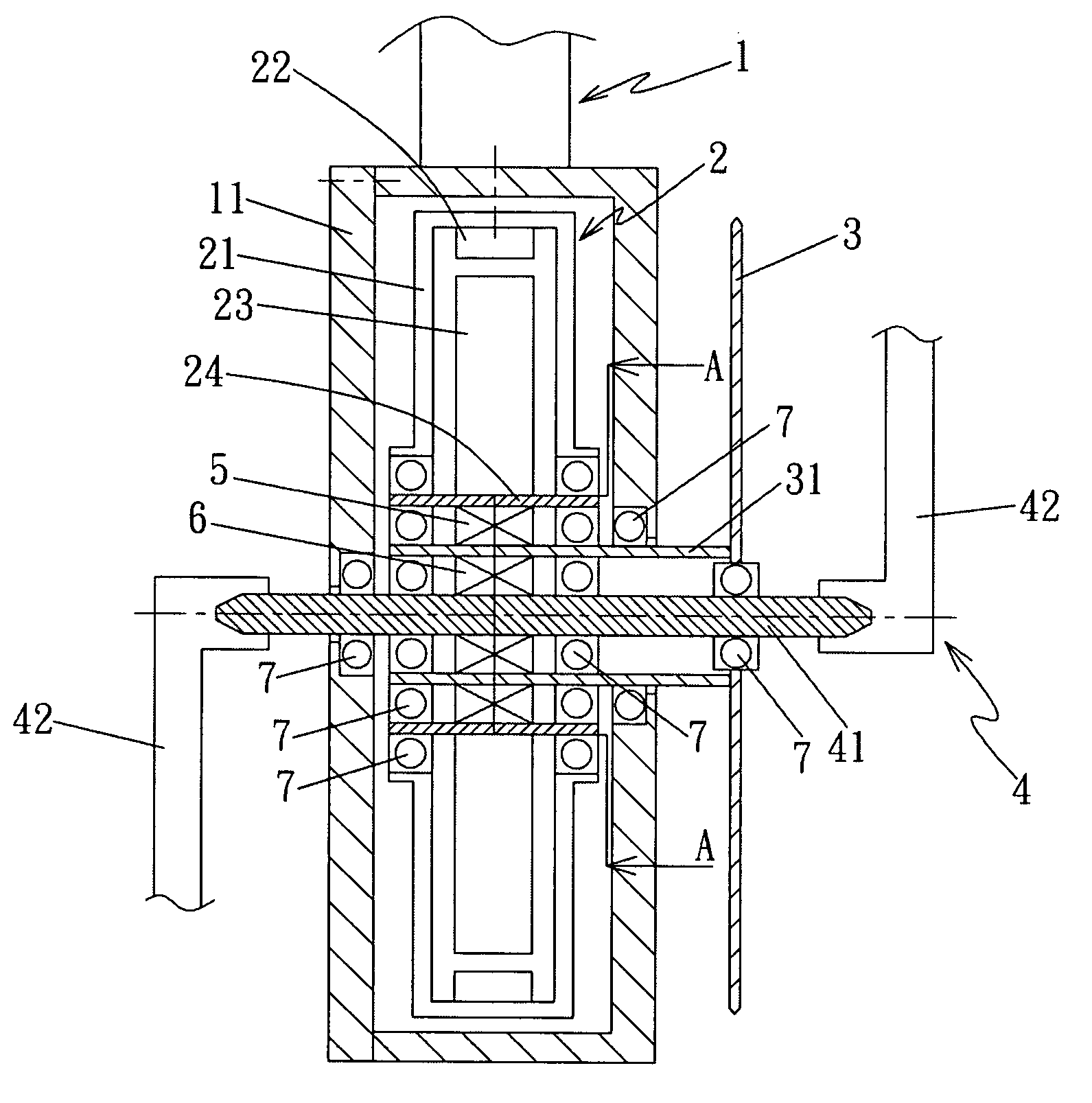
[0057]For your better understanding and recognizing the concept and technology of the present invention, some exemplary preferred embodiments with associated drawings are described below. Please firstly refer to FIG. 9, which is the integral illustrative view showing the “driving mechanism” installed in a frame manifold node 11, where is as the lower intersection of front tube and rear tube for containing pedal crank shaft in conventional bike, of the motorized bicycle 1 for the present invention. With further reference to FIG. 10 as aided illustration, the “driving mechanism for the motorized bicycle” mainly comprises a motor driving transmission device 2, a front driving sprocket 3 and a pedal driving transmission device 4, wherein,

[0058]Said motor driving transmission device 2, which is disposed on the frame manifold node 11, inwardly includes a motor shell 21, a magnet stator 22, an electromagnetic wire-coiled rotor 23 and a cylindrical hollow rotatable shaft 24 orderly in manne...


PUM


Abstract

A driving mechanism for motorized bicycle is provided. The driving mechanism comprises a motor driving transmission device, a front driving sprocket and a pedal driving transmission device. The motor driving transmission device inwardly includes a motor shell, a magnet stator, an electromagnetic wire-coiled rotor and a cylindrical hollow rotatable shaft. The front driving sprocket has a transmission rotatable sleeve disposed therein for insertion of the hollow rotatable shaft there between. The pedal driving transmission device includes a pair of pedal cranks and a pedal driving shaft passing through the transmission rotatable sleeve and hollow rotatable shaft. First and Second single direction irreversible transmission devices are arranged such that either the motor driving transmission device or pedal driving transmission device may drive the transmission rotatable sleeve and front driving sprocket in proper rotational direction.

Description

FIELD OF THE INVENTION[0001]The present invention relates to a “driving mechanism for the motorized bicycle”, particularly for one having operations of pedal driving and motor driving modes so that the effects in simple and compact structure, reducing occupied space, decreasing production cost, and balancing the transverse weight equilibrium and lowering the weight center as well as employing speed changing function to save power energy and enhance speed changing and output torque range as well as increase slope-climbing capability can be achieved.BACKGROUND OF THE INVENTION[0002]For enhancing the availability of the bicycle and reducing the physical strength burden for the bicycle rider, the various motorized bicycles that using motor driving means to replace for conventionally manually pedal driving means are introduced into the market with popular acceptance. Currently, the motor driving means of the conventional motorized bicycle are classified into four categories by transmissi...

Claims


Application Information

Patent Timeline
Patent Type & Authority Patents(United States)
IPC IPC(8): B62M23/02
CPCB62M6/55Y10T74/2165
Inventor LEE, SEN-YUNGLIN, SHUEEI-MUHSHEU, JER-JIACHENG, YUNG-CHANG
Owner GLOBAL PROSPECTIVE COOP CO
Why Eureka
Try Eureka