This helps you quickly interpret patents by identifying the three key elements:
Problems solved by technology
Method used
Benefits of technology
Problems solved by technology
[0042] (1) The alignment accuracy of the toner image and laserirradiation is low
[0043] In the transfer step, when the toner image is transferred from the photoreceptor to the recording material, the position of the recording material tends to shift due to the bending of the recording material until it is conveyed to the conveying belt.
This is the cause of deviation between the position of the toner image and the laserirradiation position
In the conventional technology described in the above-mentioned Patent Document 20, in order to cover this deviation, the image memory for changing the laserirradiation width is provided with a width change mode. At the same time, it will shorten the life of the laser light emitting device
[0044] (2) Image deterioration due to toner scattering
[0045] Since the recording material is transported to the conveyor belt after the toner is transferred, the toner may scatter when the recording material comes into contact with the conveyor belt, resulting in image degradation.
[0046] (3) Insufficient fixing
In order to make up for the lack of heat, in the prior art described in Patent Document 20, it is described that the selected toner has a low melting point and has high fixing properties even without applying pressure, but the type of toner is limited. itself will become a constraint on the entire equipment including the imaging system, resulting in the problem of low versatility
On the other hand, in the conventional technology described in Patent Document 22, a plurality of laser light sources are used to make up for the lack of power, which leads to the disadvantages of complicated equipment and high cost.
Method used
Image
Click on the blue label to locate the original text in one second.
Reading with bidirectional positioning of images and text.
Examples
Embodiment 1
[0163] First, a first embodiment of the present invention will be described.
[0164] A first embodiment of the present invention provides an image forming apparatus capable of using the toner used in the thermal fixing method while suppressing power consumption by providing both a heating method fixing device and a pressurizing method fixing device. Toner, recording materials, image forming equipment with high versatility, and while saving energy, can improve the glossiness of the toner surface to obtain an image close to photographic quality, further, according to whether glossiness is required The paper can be automatically or manually selected whether to use the function of the fixing device by pressure.
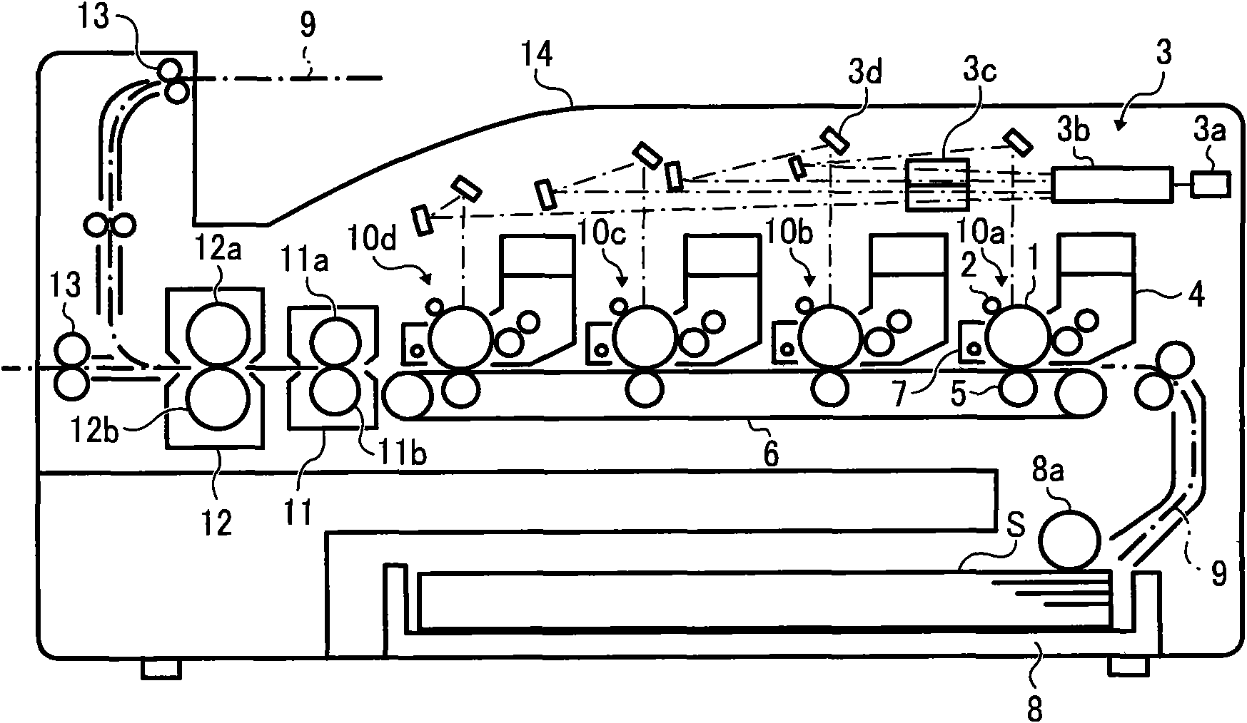
[0165] figure 1 Shown is a schematic configuration diagram of an image forming apparatus which is a configuration example of the first embodiment.
[0166] figure 1The image forming apparatus having the configuration shown in the figure is moved along a conveying be...
Embodiment 2
[0201] Next, a second embodiment of the present invention will be described.
[0202] A second embodiment of the present invention provides an image forming apparatus capable of using toner used in a thermal fixing system while suppressing power consumption by providing both a heating system fixing device and a pressure system fixing device. , recording materials, to achieve a highly versatile structure, especially the structure formed by using a heating device heated by radiant heat, and furthermore, by setting the roller pair of the fixing device of the pressurized method, it is possible to prevent the roller pair from contacting and causing damage. generated problems.
[0203] FIG. 13 is a schematic configuration diagram of an image forming apparatus as a configuration example of the second embodiment. The basic configuration, operation and figure 1 The image forming apparatuses shown are the same, and the description of Embodiment 1 can be referred to.
[0204] The pre...
Embodiment 3
[0227] Next, a third embodiment of the present invention will be described.
[0228] A third embodiment of the present invention provides an image forming apparatus capable of using toner and plain paper used in thermal fixing by providing both a heating fixing device and a pressure fixing device. With a highly versatile structure, the start time can be shortened to achieve energy saving. In addition, by setting the toner transfer process and heating process along the peripheral surface of the same recording material conveying belt, the recording material is separated from the conveying belt. By softening the toner and holding it in the recording material, it is possible to prevent toner scattering and image disturbance during separation. Furthermore, by disposing the pair of pressure rollers of the fixing device of the pressure system spaced apart, it is possible to prevent damage that may occur when the pair of pressure rollers come into contact.
[0229] Figure 20 Shown ...
PUM
Abstract
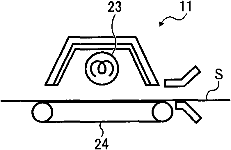
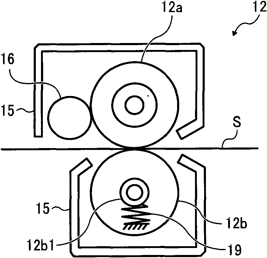
The invention provides an image forming apparatus comprising a fixing device capable of shortening start time and saving energy. The apparatus comprises an exposure device 3 that forms a latent image in an image carrier; a developing device 4 that develops the latent image formed on the image carrier through a toner; a transfer printing device 5 that prints the developed toner image on the image carrier in a recoding material S in a transfer printing manner; and a paper feeding and conveying device 8a.6 that synchronously conveys the papery recording material S piled in a paper feeding part 8and the toner image developed by the developing device to the transfer printing device. The fixing device fixes the toner image printed in the recording material in a transfer printing manner by the transfer printing device and comprises a first fixing device 11 that is arranged in the path 9 of conveying the recording material after the toner image is printed in a transfer printing manner so as to soften the toner printed in the recording material in a transfer printing manner; and a second fixing device 12 that is arranged at the downstream of the first fixing device near to the conveying direction of the recording material and used for smoothing and fixing the surface of the toner softened by the first fixing device.
Description
technical field [0001] The present invention relates to image forming apparatuses such as copiers, printers, plotters, facsimile machines, and multifunction machines thereof, and particularly to image forming apparatuses characterized by a fixing method. Background technique [0002] Conventionally, in image forming apparatuses such as copiers and printers, in order to fix the toner image transferred onto the recording material to the recording material, a configuration including a fixing device is generally employed. Then, in order to suppress the occurrence of fixing defects, many fixing methods have been disclosed. At present, the heat roller method is generally adopted, that is, the heating roller heated by the heating source is used as the fixing roller, and the fixing roller is arranged opposite to the fixing roller to form a nip. The pressure roller, the unfixed image is fixed to the recording material by the fixing roller and the pressure roller. [0003] As a fixin...
Claims
Application Information
Patent Timeline
Application Date:The date an application was filed.
Publication Date:The date a patent or application was officially published.
First Publication Date:The earliest publication date of a patent with the same application number.
Issue Date:Publication date of the patent grant document.
PCT Entry Date:The Entry date of PCT National Phase.
Estimated Expiry Date:The statutory expiry date of a patent right according to the Patent Law, and it is the longest term of protection that the patent right can achieve without the termination of the patent right due to other reasons(Term extension factor has been taken into account ).
Invalid Date:Actual expiry date is based on effective date or publication date of legal transaction data of invalid patent.

