Power control device for high-frequency dielectric heating and its control method

A technology of medium heating and power control unit, which is applied in the direction of electric heating device, electric/magnetic/electromagnetic heating, microwave heating, etc.

Active Publication Date: 2008-12-03
PANASONIC CORP
View PDF5 Cites 13 Cited by
  • Summary
  • Abstract
  • Description
  • Claims
  • Application Information

AI Technical Summary

Problems solved by technology

Therefore, if there are variations in the type and characteristics of the magnetron, or if there are fluctuations in ebm (anode-cathode voltage) caused by the temperature of the anode of the magnetron and the load in the microwave oven, or if there are fluctuations in the power supply voltage, it is not possible to Input current waveform shaping is possible by their influence

Method used


Image

  • Power control device for high-frequency dielectric heating and its control method
  • Power control device for high-frequency dielectric heating and its control method
  • Power control device for high-frequency dielectric heating and its control method

Examples


no. 1 example

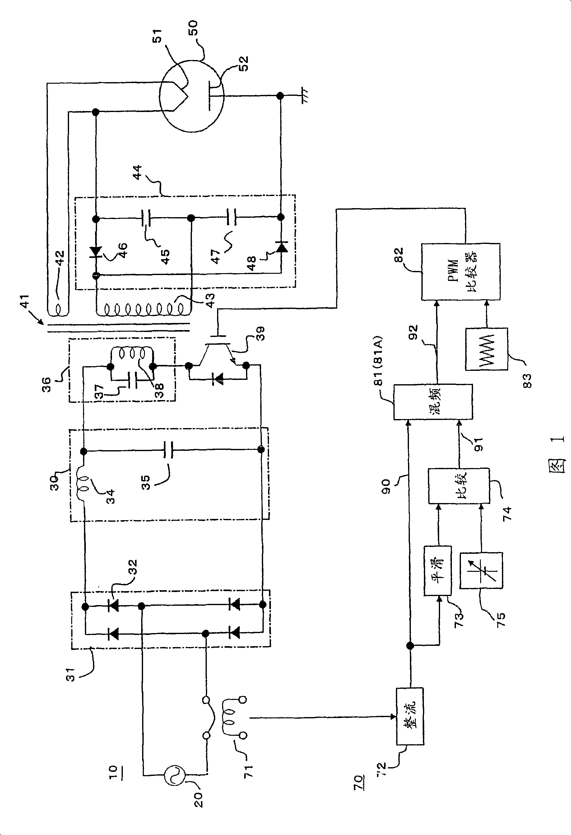
[0143] FIG. 1 is a block diagram illustrating a high-frequency dielectric heating power control unit according to a first embodiment of the present invention. In FIG. 1 , the high-frequency heating unit is composed of an inverter circuit 10 , a control circuit 70 for controlling a switching transistor 39 of the inverter, and a magnetron 50 . The inverter circuit 10 includes an AC power source 20 , a diode bridge rectification circuit 31 , a smoothing circuit 30 , a resonance circuit 36 ​​, a switching transistor 39 and a voltage amplification rectifier 44 .

[0144] The AC voltage of the AC power source 20 is rectified by a diode bridge rectification circuit 31 composed of four diodes 32 and converted into a DC voltage by a smoothing circuit 30 composed of an inductor 34 and a capacitor 35 . Then, through the resonant circuit 36 ​​and the switching transistor 39 composed of the capacitor 37 and the primary coil 38 of the transformer 41, the DC voltage is converted into high-fr...

no. 2 example

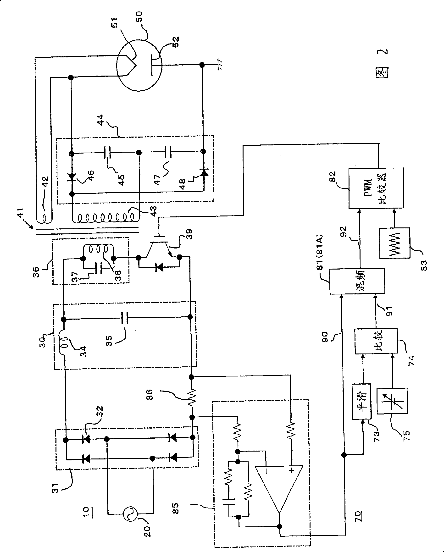
[0172] Next, a second embodiment of the present invention will be described. A second embodiment of the present invention relates to the configuration of a control circuit. Compared with the related art example in FIG. 32, except that the inverting circuit is incorporated in the mixing circuit 81A as shown in FIG. 1, the diode 261, shaping circuit 262, variable gain amplifier circuit 291, inverting and the waveform processing circuit 263 and the waveform error detection circuit 292, so that a significant reduction is achieved, the waveform error detection line is significantly simplified, the miniaturization of the machine configuration is facilitated, the control process is simplified, and the processing time can be shortened, thereby improving the machine reliability.

[0173] The input current waveform information 90 and the power control information 91 from the comparison circuit 74 are mixed, and the mixed information is filtered and converted into an on / off drive signal...

no. 3 example

[0175] The third embodiment relates to an input current detection section. As shown in FIG. 1 , the above-described input current detection section detects an input current to the inverter circuit through a CT 71 and the like, and rectifies and outputs it through a rectification circuit 72 . In this configuration, since the input current is detected using CT or the like, a large signal can be taken out while maintaining the insulation properties, making the effect of input current waveform shaping large, and improving the quality of the input current.

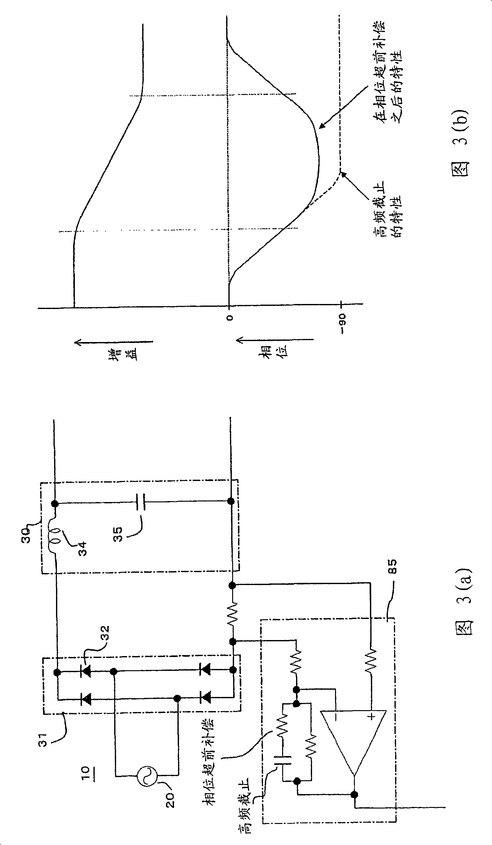
[0176] In the example shown in FIG. 2, the input current detection section detects the unidirectional current passing through the shunt resistor 86 located between the shaping circuit 31 and the smoothing circuit 30 after being shaped by the shaping circuit 31 of the inverter circuit, and passing through An amplification circuit (amplifier) ​​85 amplifies the voltage generated across the shunt resistor, and outputs the voltage....


PUM


Abstract

Provided is a power control device for high-frequency dielectric heating not affected by the magnetron type, characteristic irregularities, or power voltage fluctuation. The device includes input current detection units (71, 72) for detecting input current of an inverter circuit (10) for rectifying (31) AC source voltage (20), performing high-frequency switching, and converting it into a high-frequency power. A mixing circuit (81) mixes input current waveform information (90) on the input current detection units and power control information (91) for controlling the output of the input current detection units to be a predetermined value, thereby outputting ON voltage information (92). A PWM comparator (82) compares the ON voltage information to a saw-tooth wave from a saw-tooth wave generation circuit (83). Pulse width modulation is performed and a drive signal is outputted to perform ON / OFF control of a switching transistor (39) of the inverter circuit.

Description

technical field [0001] The present invention relates to power control of high-frequency dielectric heating using magnetrons, such as microwave ovens, and in particular, to power control that is not affected by variations in the characteristics of the magnetrons or types of characteristics, or the anode temperature of the magnetrons, etc. High frequency dielectric heating. Background technique [0002] A known high-frequency dielectric heating unit in the related art adjusts the power applied to the magnetron according to the width of an output pulse from an inverter. As the output voltage of the signal superposition section becomes higher, the output pulse width of the inverter control circuit becomes wider and the power applied to the magnetron increases. This configuration makes it possible to change the output voltage of the signal superimposing part to continuously change the heating output of the magnetron. [0003] Since the heater is also used as the cathode of the ...

Claims


Application Information

Patent Timeline
Patent Type & Authority Applications(China)
IPC IPC(8): H05B6/68H05B6/66
CPCH05B6/685
Inventor 末永治雄安井健治酒井伸一城川信夫守屋英明木下学
Owner PANASONIC CORP
Why Eureka
Try Eureka