Shift register, scanning-line drive circuit, data-line drive circuit, electro-optical device, and electronic apparatus

a technology of scanning-line drive circuit and shift register, which is applied in the direction of digital storage, instruments, computing, etc., can solve the problems of delay in the start time of discharging the first capacitor, erroneous operation or quality degradation of the device,

Inactive Publication Date: 2011-09-29
138 EAST LCD ADVANCEMENTS LTD +1
View PDF8 Cites 14 Cited by
  • Summary
  • Abstract
  • Description
  • Claims
  • Application Information

AI Technical Summary

Benefits of technology

[0013]An advantage of some aspects of the invention is that it provides a shift register that includes unit circuits for switching output levels of output signals by the operations of first and second transistors and that maintains correct switching of output levels even if the second transistor deteriorates.

Problems solved by technology

This may bring about erroneous operations or quality deterioration in a device using the shift register 200.
This delays the start time of discharging of the first capacitor.

Method used


Image

  • Shift register, scanning-line drive circuit, data-line drive circuit, electro-optical device, and electronic apparatus
  • Shift register, scanning-line drive circuit, data-line drive circuit, electro-optical device, and electronic apparatus
  • Shift register, scanning-line drive circuit, data-line drive circuit, electro-optical device, and electronic apparatus

Examples


first embodiment

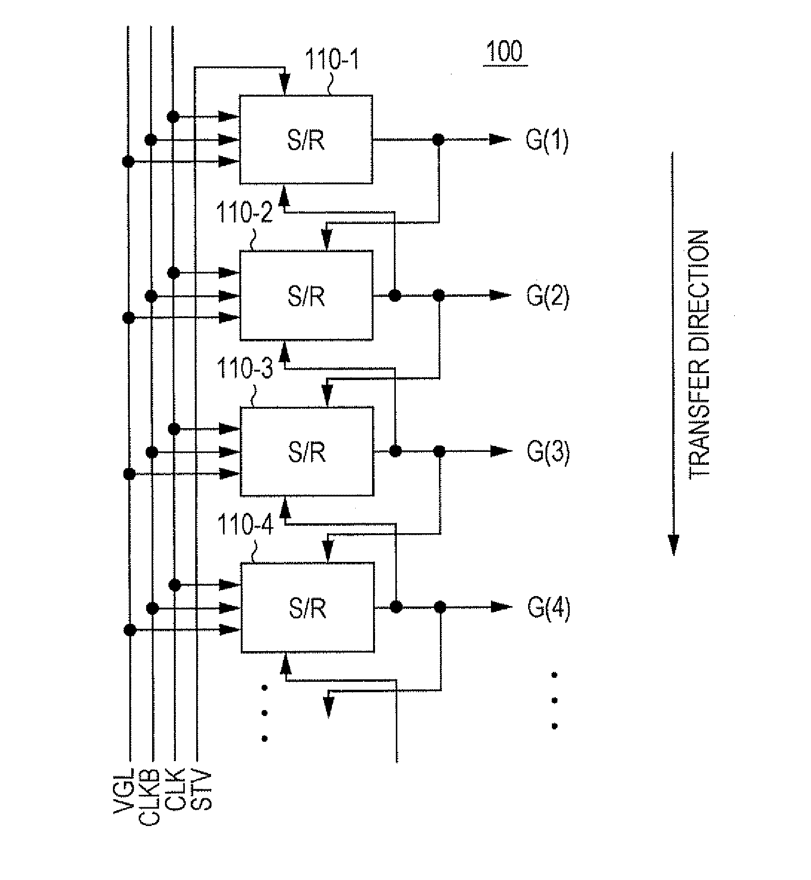
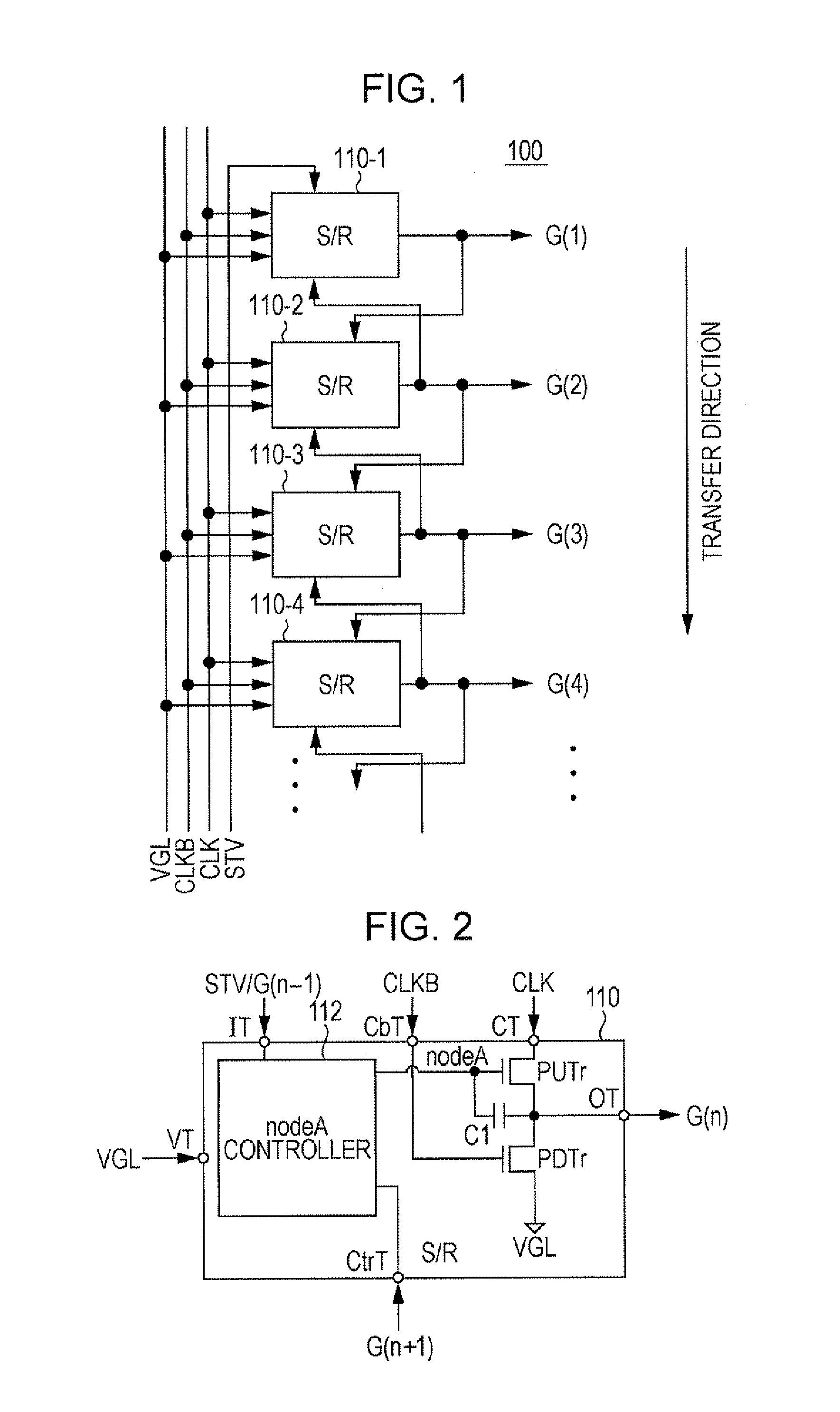
[0042]FIG. 1 is a block diagram illustrating the configuration of a shift register 100 that operates in response to two-phase clock signals according to a first embodiment of the invention. The shift register 100 includes, as shown in FIG. 1, a plurality of unit circuits 110 (110-1, 110-2, and so on). A power supply potential VGL, which serves as the reference potential of a low level signal, a clock signal CLK, and an inverted clock signal CLKB out of phase with the clock signal CLK by 180° are supplied to each unit circuit 110.

[0043]A start pulse signal STV is supplied to the input terminal of the first unit circuit 110-1, and an output signal G(n-1) of the previous unit circuit 110-(n-1) is supplied to the input terminal of each unit circuit 110-n except for the first unit circuit 110-1. An output signal G(n+1) of the subsequent unit circuit 110-(n+1) is supplied to the control terminal of each unit circuit 110-n. With this configuration, in response to the start pulse signal STV...

second embodiment

[0078]An electro-optical device 500 using the above-described shift register 100 for a drive circuit is described below.

[0079]FIG. 9 is a block diagram illustrating the electrical configuration of the electro-optical device 500 according to a second embodiment of the invention. The electro-optical device 500 employs liquid crystals as an electro-optical material. The electro-optical device 500 includes a liquid crystal panel AA as the main unit. The liquid crystal panel AA includes a device substrate on which thin-film transistors (hereinafter referred to as the “TFTs”) are formed as switching elements and a counter substrate. The device substrate and the counter substrate face each other with a predetermined gap therebetween, and the liquid crystals are interposed in this gap.

[0080]The electro-optical device 500 includes the liquid crystal panel AA, a timing generating circuit 300, and an image processing circuit 400. The liquid crystal panel AA includes, on the device substrate, a...


PUM


Abstract

A shift register including a plurality of unit circuits sequentially transfers a start signal supplied to a first one of the unit circuits. Each unit circuit includes a clock terminal, an inverted clock terminal, a control terminal to which an output signal output from the output terminal of a subsequent unit circuit is supplied, a power supply terminal, a first transistor disposed between the clock terminal and the output terminal, a second transistor disposed between the output terminal and the power supply terminal, a capacitor, and a controller that supplies the start signal or the output signal of a previous unit circuit to the gate of the first transistor, and that controls the first transistor to be turned OFF later than a time at which the output signal of the subsequent unit circuit is supplied to the control terminal.

Description

BACKGROUND[0001]1. Technical Field[0002]The present invention relates to a shift register, a scanning-line drive circuit, a data-line drive circuit, an electro-optical device, and an electronic apparatus.[0003]2. Related Art[0004]Electro-optical devices that perform display by utilizing liquid crystals or organic electronic-luminescence (EL) are widely known. In such an electro-optical device, a scanning-line drive circuit includes a shift register and generates scanning signals for sequentially selecting a plurality of scanning lines. Some of such shift registers include transistors having the same conductivity type and operate in response to two-phase clock signals. An example of such shift registers is disclosed in Japanese Patent No. 4,083,581.[0005]FIG. 13 is a block diagram illustrating the configuration of a shift register 200 operating in response to two-phase clock signals. When a start pulse signal STV is input to a first unit circuit 210-1, the shift register 200 sequenti...

Claims


Application Information

Patent Timeline
Patent Type & Authority Applications(United States)
IPC IPC(8): G09G5/00G11C19/28
CPCG09G3/20G09G2310/0286G09G2310/0267
Inventor YOSHII, TAKASHIHIRABAYASHI, YUKIYASHIMIZU, KOJI
Owner 138 EAST LCD ADVANCEMENTS LTD
Why Eureka
Try Eureka