Dynamic indication guiding illuminating line

A technology of dynamic indication and lighting lines, applied in the field of safety and lifesaving lighting, to achieve the effect of improving the efficiency of luminous reflection

Active Publication Date: 2013-04-03
SHANGHAI KERUN PHOSPHOR TECH
View PDF9 Cites 8 Cited by
  • Summary
  • Abstract
  • Description
  • Claims
  • Application Information

AI Technical Summary

Problems solved by technology

Use transparent plastic 6 seals to form multi-core electroluminescent wires

Method used


Image

  • Dynamic indication guiding illuminating line
  • Dynamic indication guiding illuminating line

Examples


Embodiment

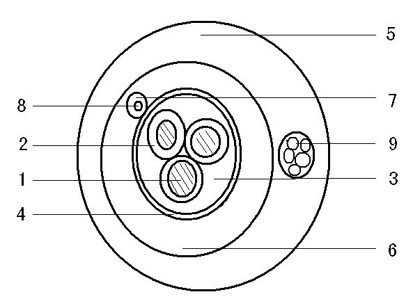
[0048] Three continuous 600 m lengths of 0.2 mm diameter copper wires were coated with a titanium dioxide dielectric layer approximately 10 microns thick and dried.

[0049] Then three wires coated with a dielectric layer are spirally twisted together according to the rules to form a multi-core inner electrode of a multi-core electroluminescent wire, and the three inner electrodes are mutually insulated.

[0050] The surface of the multi-core internal electrode is coated with an electroluminescent layer at one time, with a thickness of about 50 microns, and dried.

[0051] Coating an ITO transparent conductive layer outside the electroluminescent layer and drying it.

[0052] The transparent conductive layer is in continuous contact with a flexible external electrode, the diameter of which is 0.3mm, and the flexible external electrode is wound helically. A 0.5 mm wide copper-plated aluminum foil is continuously wound on the outside of the nylon wire to form a flexible outer e...


PUM


Abstract

A dynamic indication guiding illuminating line comprises a multi-core electroluminescent line, a multi-output electroluminescent line drive and a power source. The dynamic indication guiding illuminating line is characterized in that dielectric layers are coated on the surfaces of three continuous metal wires which are spirally wound to form a multi-core electrode, an electroluminescent layer is coated on the surface of the multi-core electrode for one time, a transparent conducting layer which is in continuous contact with an outer flexible electrode is coated outside the electroluminescent layer, and transparent plastic is used for sealing to form the multi-core electroluminescent line. When the dynamic indication guiding illuminating line is used, the multi-core electroluminescent line, the multi-output electroluminescent line drive and the power source are in series connection to form directional flowing luminescence. The guiding illuminating line for firefighting is mainly applied to rescuing at places such as markets, subways, coal mines and fields to guide trapped people to evacuate according to target directions.

Description

technical field [0001] The invention belongs to the safety and lifesaving lighting technology in the field of lighting. technical background [0002] Safety-oriented lighting is mainly used in: shopping malls, subways, coal mines and other large closed places with complex passages and wild night rescue, guiding trapped people to evacuate according to the planned target direction, and clearly guiding the passage route. [0003] The prior art uses LED or neon bulb lighting sources, which are point light sources arranged in series, so they are also called string lights, and their original purpose is mainly used for outdoor decorative lighting during festivals. The shortcomings of the existing technology are: the point light source does not emit light continuously, and the direction cannot be recognized at a short distance indoors; the power consumption is large, 2-7 watts per meter, and a large supporting battery is required as a power supply; the diameter of the light-emittin...

Claims


Application Information

Patent Timeline
Patent Type & Authority Applications(China)
IPC IPC(8): H05B33/12
Inventor 郑岩耿树范边静宇史陈峰张凤琴孟立建徐征余锡宾
Owner SHANGHAI KERUN PHOSPHOR TECH
Why Eureka
Try Eureka