Combined radio frequency identification and optical imaging module

a radio frequency identification and optical imaging technology, applied in the field of data collection systems, can solve the problems of lack of image processing ability, lack of true image data, and rudimentary conventions of barcodes and rfids, and achieve the effect of easy integration into a new system

Active Publication Date: 2010-08-03
NOVANTA CORP
View PDF21 Cites 10 Cited by
  • Summary
  • Abstract
  • Description
  • Claims
  • Application Information

AI Technical Summary

Benefits of technology

[0007]It is a principal object and advantage of the present invention to provide a modular and scalable system that combines RFID and optical imaging capabilities.
[0008]It is an additional object and advantage of the present invention to provide a modular and scalable system that combines RFID and optical imaging capabilities that is controllable via a host computer.
[0009]It is a further object and advantage of the present invention to provide a modular and scalable system that combines RFID and optical imaging capabilities that is field programmable.
[0010]It is another object and advantage of the present invention to provide a field programmable module capable of custom image processing.
[0011]Other objects and advantages of the present invention will in part be obvious, and in part appear hereinafter.
[0012]In accordance with the foregoing objects and advantages, the present invention comprises a modular and scalable system for integrating two or more subsystems into a host controlled device. More particularly, the present invention is capable of integrating an optical imager and a RFID reader with a single host interface. The invention includes a system microcontroller that interconnects an optical image capture subsystem and a RFID subsystem through a single interface to a host computer. The system microprocessor is configurable via the host interface to selectively provide RFID reading or writing, optical imaging, barcode reading, or a variety of combinations of both techniques. The module is programmed to allow the host computer to trigger the RFID reader and optical imager. In addition, the system microcontroller is programmable via the host computer to provide image analysis, such as shape determination or recognition, prior to relaying data to the host computer through the single interface. Further, the implementation of each of the interfaces to imager, host computer, and RFID functions can be configured to be physically and electrically identical. This variations in the functionality delivered by the module while maintaining a single connection to the host compture. The present invention may be easily retrofit into a pre-existing system and programmed to perform a variety RFID and optical imaging tasks previously unavailable to the system, or easily integrated into a new system without the need for additional hardware and software for performing image and interrogation data processing.

Problems solved by technology

Conventional systems for utilizing barcodes and RFID are often rudimentary, particularly in the medical field.
However, the information recognized by these systems is simply the presence of absence of the device or predetermined indicia.
As a result, there is no true image data, the systems lack the ability to process images, and the methods used to communicate the results to the host system are rather limited.
In addition, it is often not practical or easy to place indicia on devices that, for example, must withstand the temperatures and process of sterilization.
Moreover, the process or expense necessary of accurately place indicia or RFID tags on legacy medical devices may outweigh the feasible of using more advanced systems.
These systems are not, however, capable of combining the advantages of machine vision and RFID into a modular package that may be easily integrated into existing medical devices or adapted for use in new systems and easily controlled by the user.

Method used


Image

  • Combined radio frequency identification and optical imaging module
  • Combined radio frequency identification and optical imaging module
  • Combined radio frequency identification and optical imaging module

Examples


Embodiment Construction

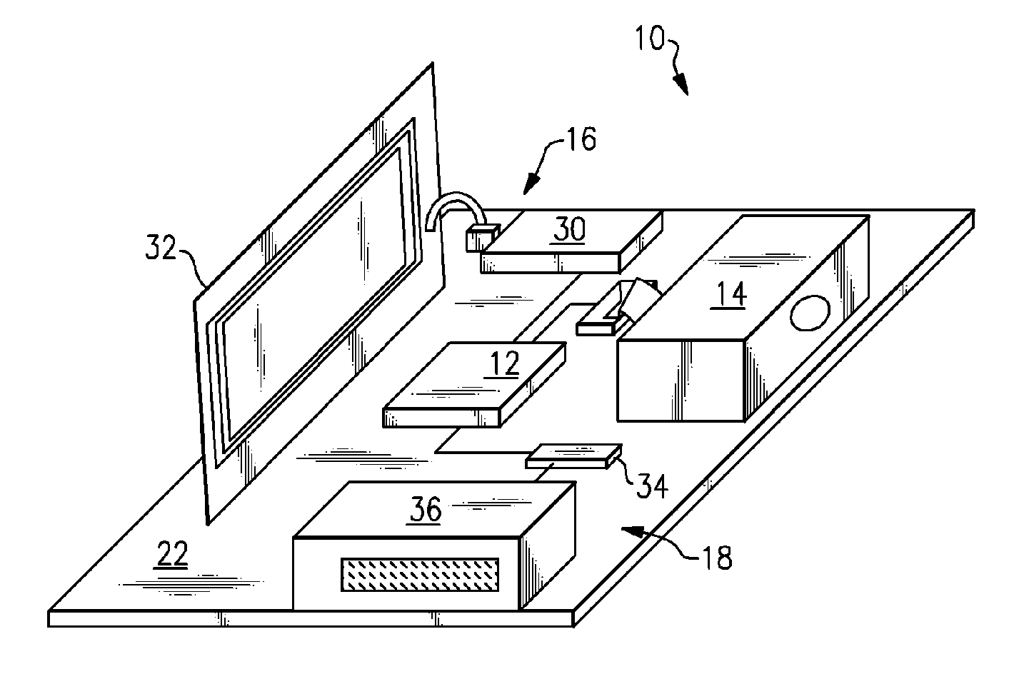
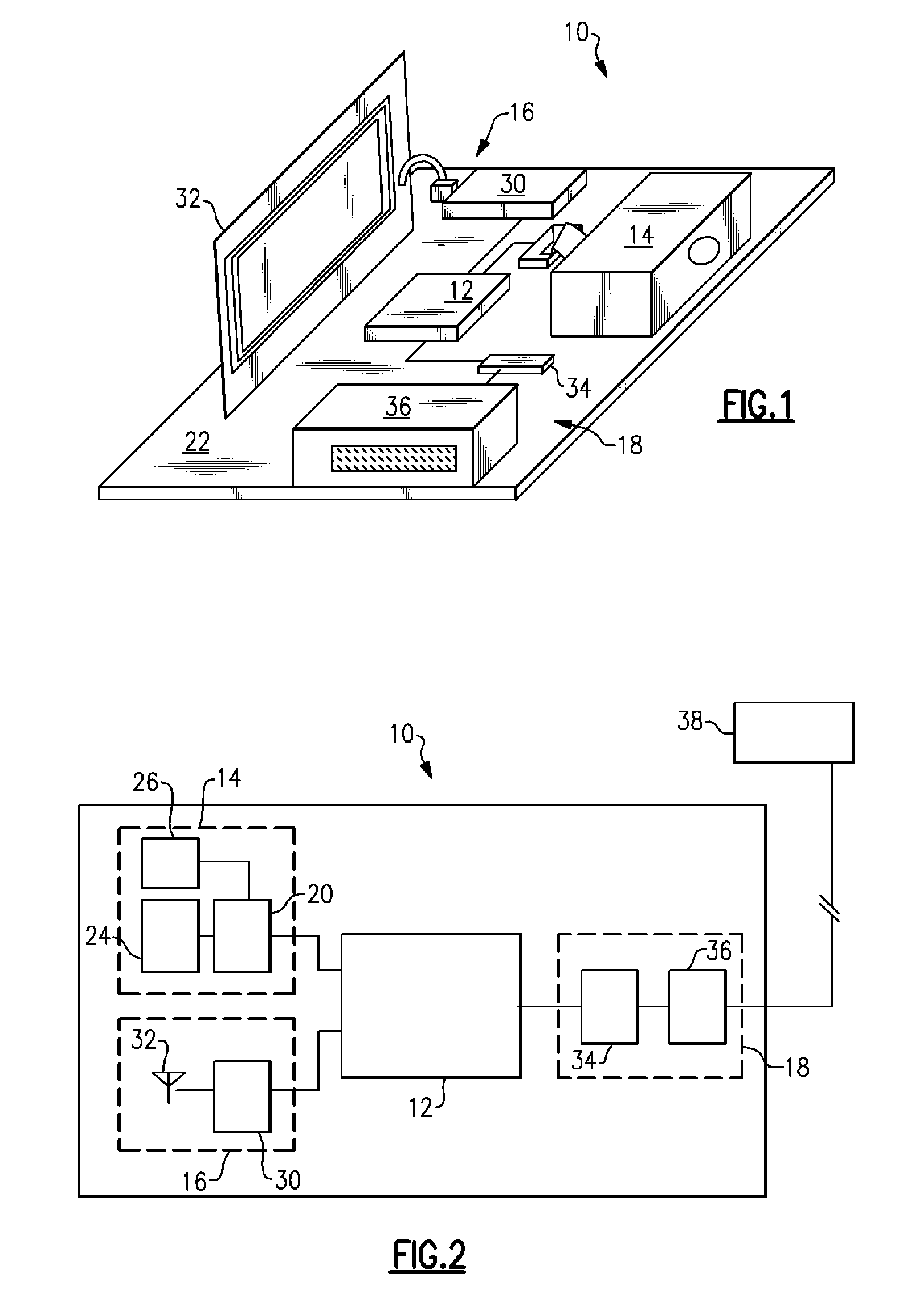
[0018]Referring now to the drawings, wherein like numerals refer to like parts throughout, there is seen in FIG. 1 a combined RFID and optical image module 10 according to the present invention. Module 10 generally comprises a microcontroller 12 that interconnects a first submodule, such as an optical imager 14, and a second submodule, such as a RFID unit 16, to a single host interface 18. Alternatively, module 10 is capable of interconnecting any variety of data capturing devices as submodules and providing host controllability, including optical imagers, RFID transceivers, lasers, scales, thermometers or temperature probes, etc., in any variety of combinations. Module 10 may be arranged on a single printed circuit board 22 and encased as a single unit or housing. Integration of imager 14 and RFID unit 16 through interface 18 allows for combining control of operation of both submodules, such as RFID reading and barcode, through module 10, as will be explained in detail hereinafter....


PUM


Abstract

An optical imager, a RFID reader, and a single host interface combined into a single module for use as a stand alone device or OEM product. The module includes a system microcontroller that interconnects an optical image microcontroller and a RFID microcontroller through the single interface to a host device, such as a computer. The system microprocessor is configurable via the host interface to selectively provide RFID reading, optical imaging, or a variety of combinations of both techniques. The module is programmable to allow the host computer trigger the RFID reader and optical imager. In addition, the system microcontroller is programmable via the host computer to provide image analysis, such as shape determination or recognition, prior to relaying data to the host computer through the single interface.

Description

FIELD OF INVENTION[0001]The present invention relates to data collection systems and, more specifically, to a system and method for combining radiofrequency identification and optical imaging into a host controllable module.DESCRIPTION OF PRIOR ART[0002]Barcodes are essentially graphic representation of data (alpha, numeric, or both) that is machine-readable. Barcodes encode numbers and letters into different types of symbologies, such as linear codes, two-dimensional codes, and composite codes (a combination of linear and two-dimensional codes). In more recent applications, referred to as digital or optical image capture, an optical device snaps a digital picture of the barcode and software in the imager orients the picture and decodes the barcode(s) contained in the picture.[0003]Radiofrequency identification (RFID) is a wireless communication technology that utilizes radiowaves for automatic identification and data capture of information for the purpose of identifying and trackin...

Claims


Application Information

Patent Timeline
Patent Type & Authority Patents(United States)
IPC IPC(8): G06K7/06G06K7/04
CPCA61B19/44A61M5/142G06F19/3462A61B2017/00017A61B2017/00119A61B2017/00482A61B2019/442A61B2019/448A61M2205/6054A61M2205/6063A61B90/90A61B90/96A61B90/98G16H20/13
Inventor MILLER, DAVID PAUL
Owner NOVANTA CORP
Why Eureka
Try Eureka