Ink supply method and printing apparatus

a technology of printing apparatus and supply method, which is applied in the field of supply method, can solve the problems of deterioration of gas-liquid separation capability, difficulty in reducing the size of printing apparatus, and increasing the price of apparatus, so as to improve the durability and reliability of gas-liquid separation member, and thus the reliability of printing apparatus.

Inactive Publication Date: 2010-08-03
CANON KK
View PDF12 Cites 16 Cited by
  • Summary
  • Abstract
  • Description
  • Claims
  • Application Information

AI Technical Summary

Benefits of technology

[0021]It is an objective of the present invention to provide an ink supply method and a printing apparatus by which, when ink supply is repeated by using a gas-liquid separation member, damage to the gas-liquid separation member is reduced to improve the reliability.
[0027]According to the present invention, an ink supply method for supplying ink into an ink container by aspirating air in the ink container via a gas-liquid separation member sets a plurality of suction amounts of the air in the ink container per a unit time, thereby providing different ink flows in the ink container. As a result, intensive damage to the gas-liquid separation member that is caused when the ink flow is fixed can be dispersed. This can reduce, when an ink supply operation is repeated by using the gas-liquid separation member, intensive damage to the gas-liquid separation member, thereby improving the durability and reliability of the gas-liquid separation member and thus the reliability of the printing apparatus.
[0028]More specifically, defoaming points as a damage point caused in the gas-liquid separation member can be dispersed to improve the durability of the gas-liquid separation member, thereby preventing ink from leaked from the gas-liquid separation member.

Problems solved by technology

In the case of the latter tank cartridge method, the ink cartridge 1c at the printing apparatus body is connected to the printing head 1 at the carriage 1a via the ink supply tube 1d, which causes a complicated ink supply mechanism to make it difficult to reduce the size of the printing apparatus.
However, the control of the ink amount using the sensor as described above is complicated, thus causing the resultant apparatus to have an increased price.
When an ink supply to the ink reservoir portion R is repeated, a risk may be caused in which a high pressure caused at the defoaming point 17R deteriorates the gas-liquid separation capability of the gas-liquid separation member 33 at the defoaming point 17R.
When the gas-liquid separation capability of the gas-liquid separation member 33 is decreased, a risk may be caused in which ink gradually leaks from the gas-liquid separation member 33 to the exhaust path 36.
When the gas-liquid separation capability of the gas-liquid separation member 33 is decreased, a risk may be caused in which a large amount of ink leaks to the exhaust path 36 to deteriorate the air permeability of the gas-liquid separation member 33 to prevent ink from being supplied properly.
When ink leaks from the air inlet 15 to outside, a risk may be caused in which the interior of the ink jet printing apparatus is soiled or a printing medium is soiled during a printing operation.

Method used


Image

  • Ink supply method and printing apparatus
  • Ink supply method and printing apparatus
  • Ink supply method and printing apparatus

Examples


Embodiment Construction

[0040]Hereinafter, an embodiment of the present invention will be described with reference to the drawings.

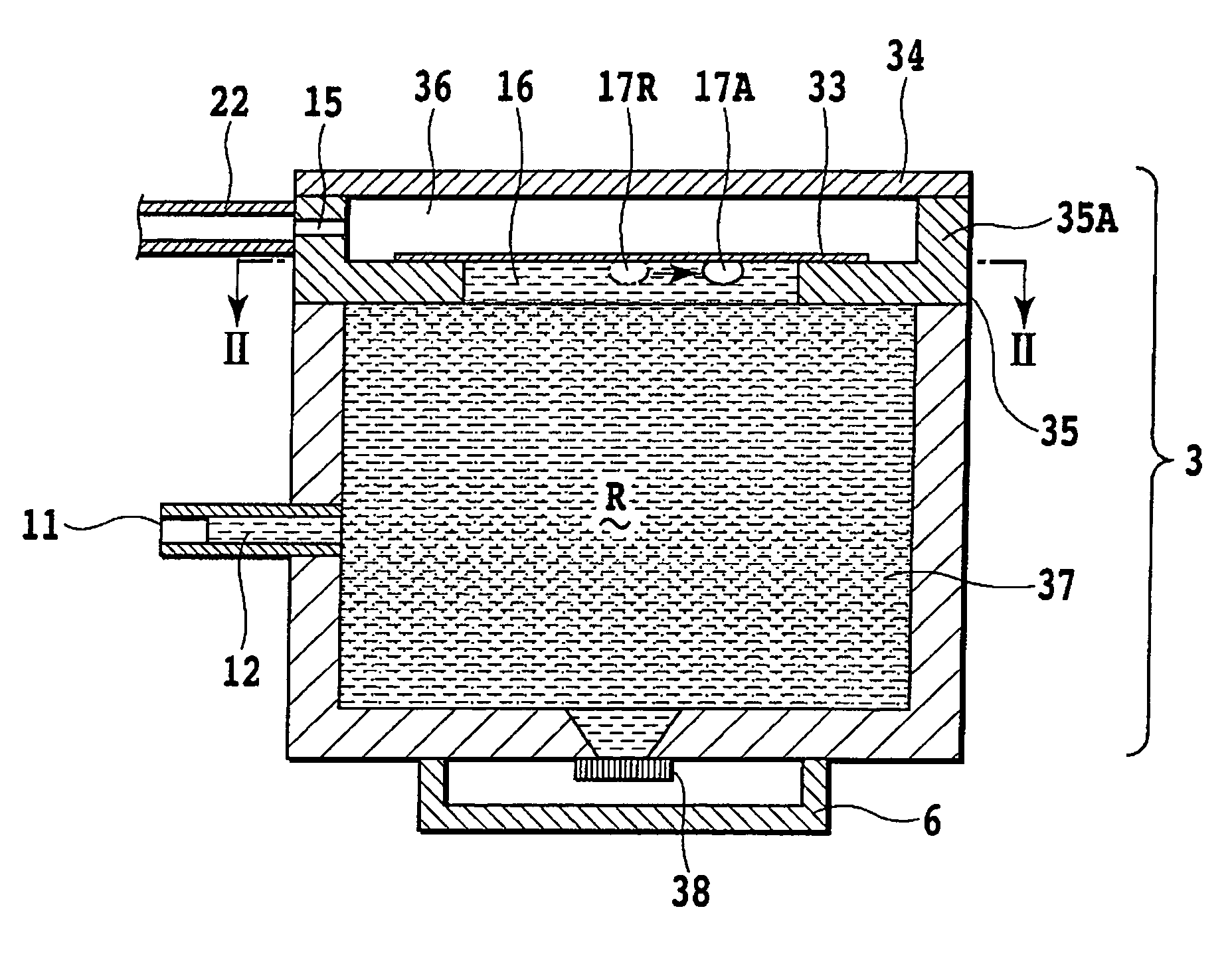
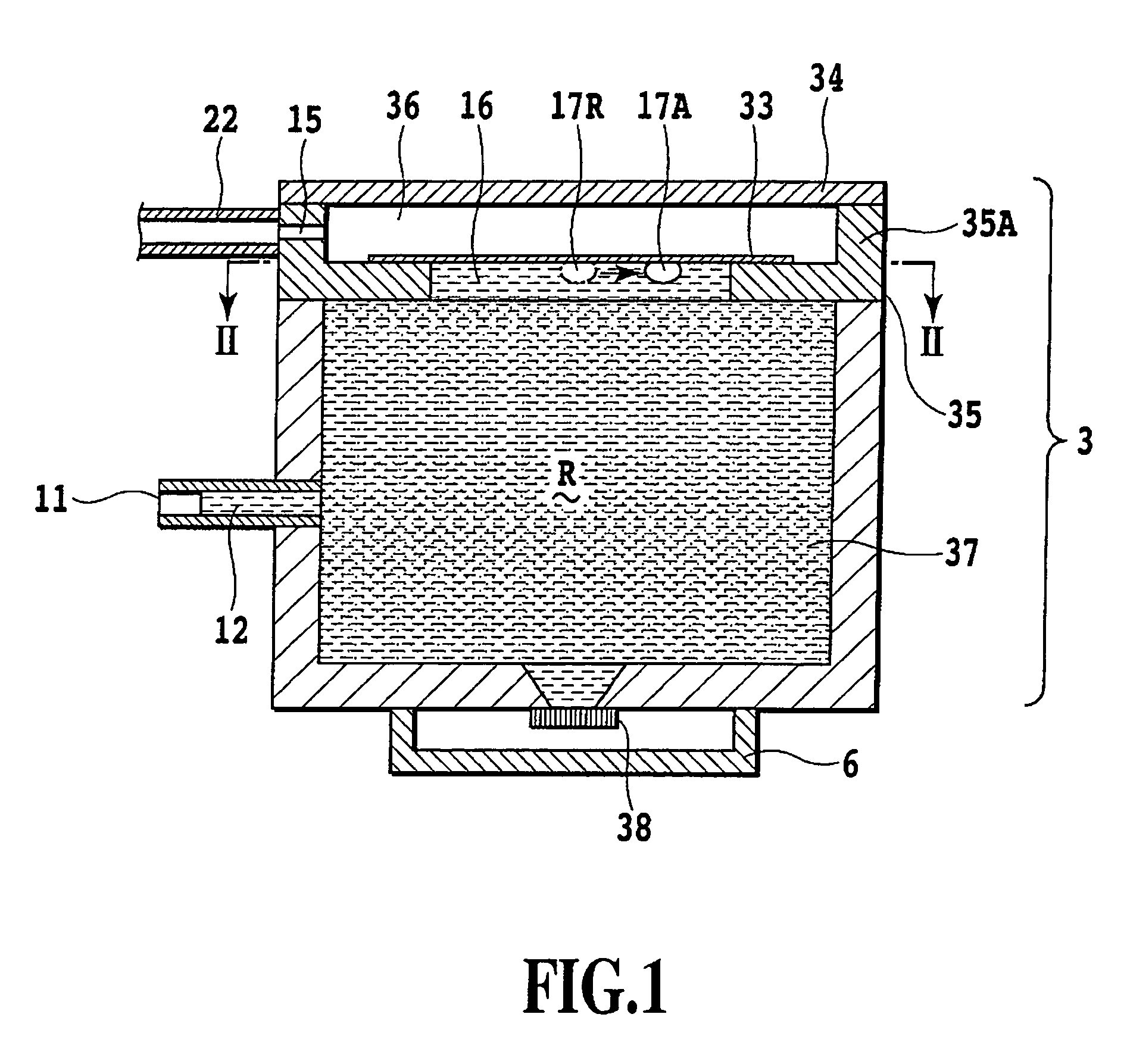
[0041]FIG. 3 is a perspective view illustrating the main part of a pit-in type ink jet printing apparatus in this embodiment. In order to print a printing paper (printing medium) 20 transported by a paper feeding roller 21, a printing head is mounted on a carriage 11a of a serial scan type ink jet printing apparatus. The printing head has the same structure as that of FIG. 5 and FIG. 6 as in FIG. 1 and FIG. 2 and includes a sub tank (ink container) 3 and an ink jet printing element 38. A carriage 1a is guided by a guide axis 8 and is engaged with a lead screw 9. When the lead screw 9 is rotated, the carriage 1a is moved along the guide axis 8 in the main scanning direction shown by the arrow X.

[0042]The main tank 4 for storing therein ink to be supplied to the sub tank 3 is provided at the predetermined home position 23 at the body of the printing apparatus. This main tank 4 in...


PUM


Abstract

The present invention relates to an ink supply method and a printing apparatus by which, when an ink supply operation is repeated by using a gas-liquid separation member, damage to the gas-liquid separation member can be reduced to improve the reliability. In order to realize this, an ink supply method for aspirating air in a sub tank via the gas-liquid separation member to supply ink from a supply opening into the sub tank sets a plurality of different amounts as an suction amount of air in the sub tank per a unit time.

Description

BACKGROUND OF THE INVENTION[0001]1. Field of the Invention[0002]The present invention relates to an ink supply method for supplying ink to an ink container and a printing apparatus using the ink supply method. In particular, the present invention relates to an ink supply method for supplying ink by using a gas-liquid separation member that permits gas to pass therethrough and that prevents liquid from passing therethrough and a printing apparatus.[0003]2. Description of the Related Art[0004]One of conventional ink jet printing apparatuses is shown in FIG. 9. This ink jet printing apparatus is a serial scan-type printing apparatus in which a printing operation is performed by moving a printing head 1 on a printing medium in a main scanning direction of an arrow X while the printing head 1 is guided by a guide axis 8. This method as shown in FIG. 9 is a so-called head cartridge method that is one of methods for supplying ink to the printing head 1. In this head cartridge method, a hea...

Claims


Application Information

Patent Timeline
Patent Type & Authority Patents(United States)
IPC IPC(8): B41J2/175
CPCB41J2/17509
Inventor TANIGUCHI, SUGURUMIZUTANI, MICHINARI
Owner CANON KK
Why Eureka
Try Eureka