Object having a layer of conducting material forming a sensing device

a technology of conducting material and sensing device, which is applied in the direction of screw, measurement apparatus components, material thermal analysis, etc., can solve the problems of not being able to easily be positioned at a desired location, difficult to do in a cost-effective and sufficiently sealed manner, and unable to achieve the effect of convenient positioning

Active Publication Date: 2010-08-03
DANFOSS PAUER SOLYUSHENS APS
View PDF47 Cites 27 Cited by
  • Summary
  • Abstract
  • Description
  • Claims
  • Application Information

AI Technical Summary

Benefits of technology

[0008]It is, thus, an object of the invention to provide a sensing device which may easily be positioned in a location which is not readily accessible.

Problems solved by technology

This has turned out to be relatively difficult, partly because in some cases the sensing devices must be resistant to relatively hostile environments in terms of temperature, pressure, corrosion promoting substances, etc., partly because wires or the like for communicating signals to / from the sensing device must be lead through an outer wall surrounding the location of the relevant sensing device, which is difficult to do in a cost-effective and sufficiently sealed manner.
The temperature sensor of U.S. Pat. No. 4,419,652 can not readily be positioned at a desired location in a sufficiently sealed manner, since an engagement between the circumferential protuberance and a metal fixturing shell is needed in order to position the temperature sensor.
Clearly, the device of U.S. Pat. No. 5,573,335 can not be readily positioned at a desired position in a sufficiently sealed manner.

Method used


Image

  • Object having a layer of conducting material forming a sensing device
  • Object having a layer of conducting material forming a sensing device
  • Object having a layer of conducting material forming a sensing device

Examples


Embodiment Construction

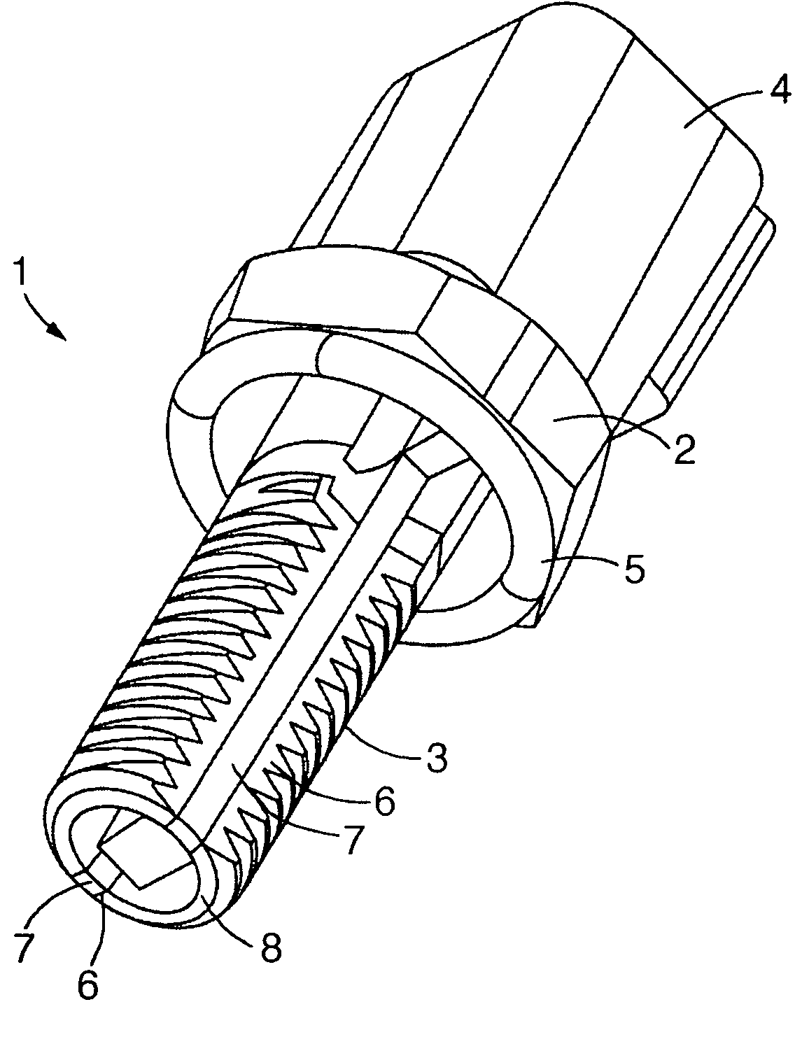
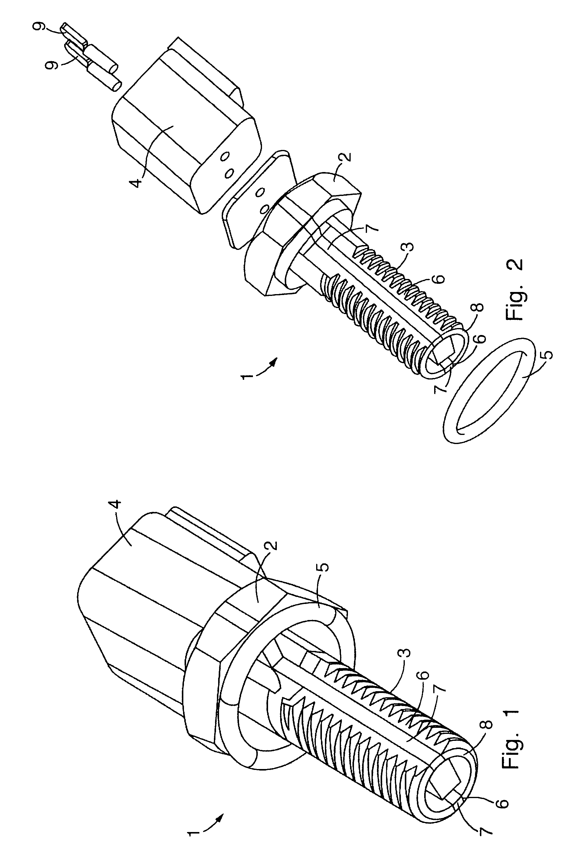
[0046]FIG. 1 is a perspective view of an object 1 in the form of a bolt. The object 1 is provided with a bolt head 2 adapted to engage a driving tool, such as a spanner, and a threaded portion 3. At the bolt head 2 the object 1 is connected to a connector box 4 for communicating signals from the object 1 to an external device. Also at the bolt head 2 is arranged an O-ring 5. Thereby the object 1 may be fitted tightly in an opening being provided with a mating inner thread.

[0047]The threaded portion 3 is provided with two sub-portions 6 where the thread is interrupted, i.e. there are no ‘hills’ and ‘valleys’ in the sub-portions 6, and the surface is therefore relatively smooth. The sub-portions 6 extend over the entire length of the threaded portion 3, thereby making it possible to establish an uninterrupted connection from one end of the threaded portion 3 to an opposite end of the threaded portion 3 along each of the sub-portions 6. Accordingly, a layer of electrically conducting m...


PUM

PropertyMeasurementUnit
electrically conductingaaaaaaaaaa
areaaaaaaaaaaa
electrically insulatingaaaaaaaaaa

Abstract

An object comprising a body part having an electrically insulating outer surface part, and a first layer arranged on the outer surface part. The first layer is formed by one or more electrically conducting materials and defines one or more conducting paths between a first area of the outer surface part and a second area of the outer surface part. Thereby electrical signals may be transferred between the first and second area parts. The layer further defines a sensing device, which is thereby embedded into the object. The object is provided with a threaded portion defining an outer thread. Thereby the object may easily be fitted into an opening having a mating inner thread. The object may be in the form of an ordinary bolt with a sensing device embedded in a surface part thereof.

Description

CROSS REFERENCE TO RELATED APPLICATIONS[0001]Applicant hereby claims foreign priority benefits under U.S.C. §119 from Danish Patent Application No. PA 2006 00493 filed on Apr. 6, 2006, the contents of which are incorporated by reference herein.FIELD OF THE INVENTION[0002]The present invention relates to an object having a layer of electrically conducting material formed on an electrically insulating surface part, the electrically conducting layer forming a sensing device. Thereby the sensing device is embedded in the object. The object is provided with a threaded portion defining an outer thread, and is thereby adapted to be attached to another object being provided with a mating inner thread.BACKGROUND OF THE INVENTION[0003]It is often desirable to perform various measurements, such as temperature measurements, pressure measurements, strain measurements, moisture measurements, etc. at locations which are not readily accessible. Such locations may, e.g., be inside a motor or a close...

Claims


Application Information

Patent Timeline
Patent Type & Authority Patents(United States)
IPC IPC(8): G01K1/08G01K7/00G01K13/00
CPCG01D11/245G01D11/30G01K1/14G01K7/02G01L1/22G01L1/2231G01L5/0004G01L9/0072G01K2217/00
Inventor WEPPENAAR, NICKYMATHIASEN, KEN ALLANNIELSEN, LARS PLETHHANSEN, MADS KOGSGAARD
Owner DANFOSS PAUER SOLYUSHENS APS
Why Eureka
Try Eureka