Power connector and power connector assembly with contact protection mechanism

a protection mechanism and power connector technology, applied in the direction of coupling contact members, coupling device connections, electric discharge lamps, etc., can solve the problems of affecting the affecting the reliability affecting the service so as to increase the reliability and life of the power connector. the effect of increasing the li

Inactive Publication Date: 2010-08-03
ALLTOP ELECTRONICS SU ZHOU
View PDF6 Cites 10 Cited by
  • Summary
  • Abstract
  • Description
  • Claims
  • Application Information

AI Technical Summary

Benefits of technology

[0006]Accordingly, an object of the present invention is to provide a power connector which can reduce the possibility of entering of foreign particles into a contact of the power connector, and the reliability and life time of the power connector can accordingly be increased.

Problems solved by technology

As the insertion opening of the receptacle contact is so narrow that it is not easy to insert the plug contacts into corresponding receptacle contacts.
Moreover, harmful deformation of the cantilever beams may occur because of improper distribution of pressure during mating of the plug and receptacle contacts.
Further, the environmental situations of the power connectors can be very bad, and foreign particles may enter into the contacts for instance into the mating space of the receptacle contacts, which might result in deformation or failure of the contacts.

Method used


Image

  • Power connector and power connector assembly with contact protection mechanism
  • Power connector and power connector assembly with contact protection mechanism
  • Power connector and power connector assembly with contact protection mechanism

Examples


Embodiment Construction

[0037]The present invention will now be described more fully with reference to the accompanying drawings, in which exemplary embodiments of the invention are shown.

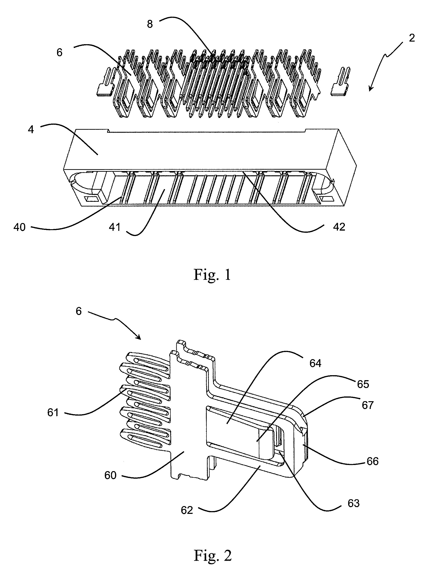
[0038]Referring to FIG. 1, the plug connector 2 comprises a plug housing 4, a plurality of plug contacts 6 for transmitting power and a plurality of plug signal contacts 8.

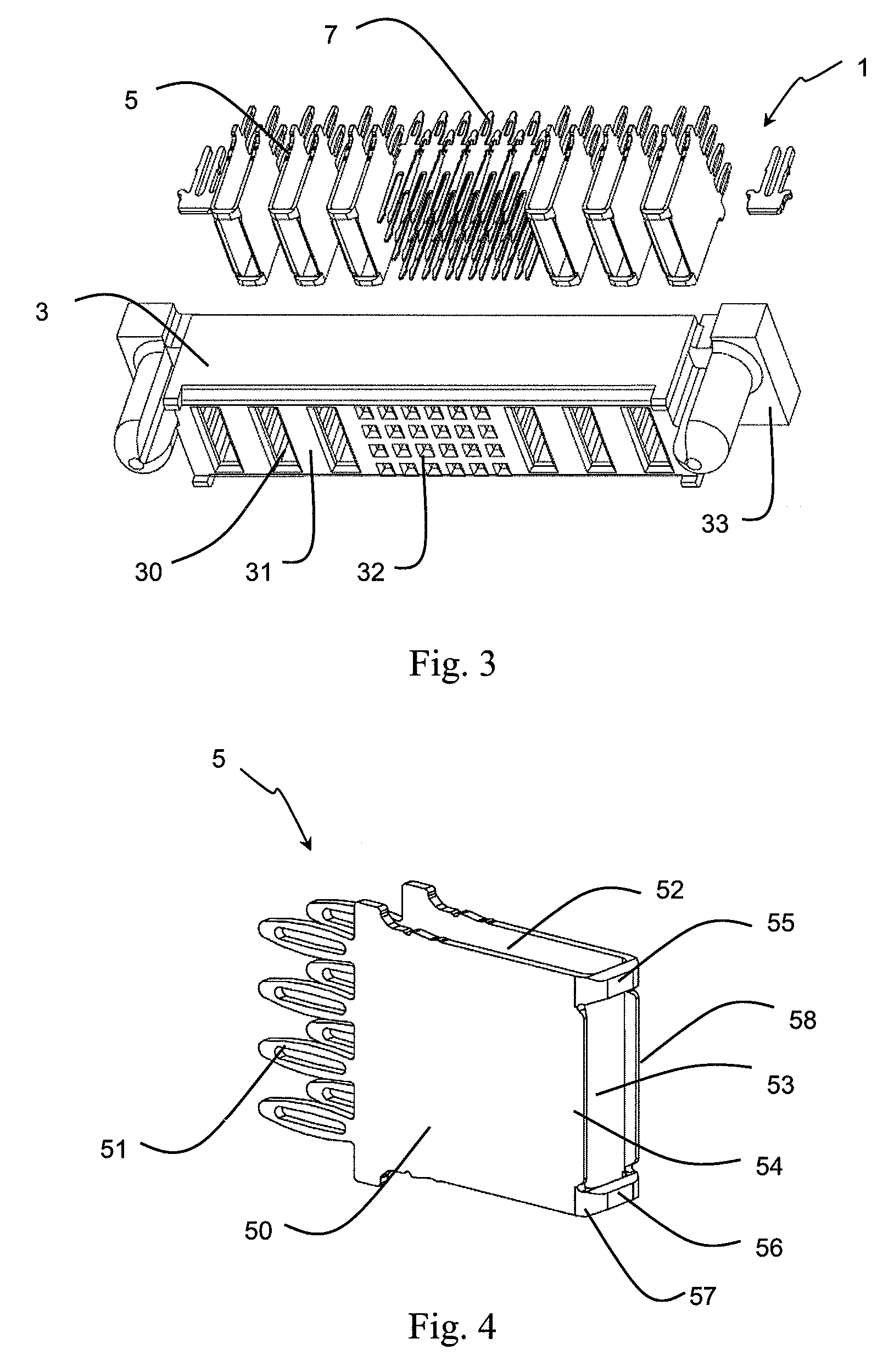
[0039]In this embodiment, the plug housing 4 has a shape of cube. The plug housing 4 has a plurality of passages 40 to receive and retain the corresponding contacts 6, 8. The plug housing 4 has a slot 41 therein. The contact portions (to be described with more details below) are disposed in the slot 41. The front surface 42 of the plug connector 2 forms a mating surface. When mating with a receptacle connector 1, the front surface 42 is in contact with a corresponding mating surface of a receptacle housing 3 of the receptacle connector 1.

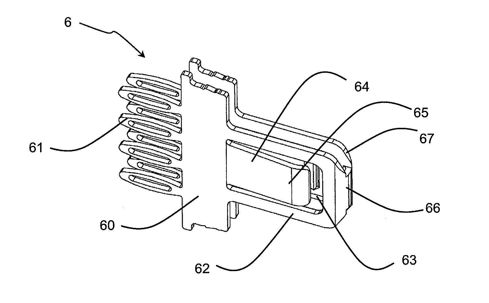
[0040]Each of the plug contacts 6 has the same structure; therefore only one of them will be described in details. Re...


PUM


Abstract

The present invention relates to a power connector. The power connector includes a housing and a number of contacts received in the housing. At least one of the contacts includes a pair of opposite walls spaced apart at a predetermined distance. The walls have a front end respectively. The contact may further include a contact protection mechanism for protecting the contacts, wherein the contact protection mechanism bridges the front ends of the walls. The present invention also relates to a power connector assembly.

Description

BACKGROUND OF THE INVENTION[0001]1. Field of the Invention[0002]The present invention relates to a power connector and a power connector assembly, and more particularly, to a power connector and a power connector assembly with contact protection mechanism adapted to transmit power between circuit boards or backplane connection systems.[0003]2. Description of Related Arts[0004]Power connectors are known from the prior art. For instance, U.S. Pat. No. 6,319,075 discloses a power connector assembly for transmitting electricity between two circuit boards or backplane connection systems. The power connector assembly includes a plug connector and a receptacle connector which comprises an insulation housing and a plurality of power contacts received therein, respectively. Each of the power contacts comprises a terminal portion to be attached to a corresponding circuit board so as to establish mechanical and electrical connections to the circuit board. The receptacle power contacts each com...

Claims


Application Information

Patent Timeline
Patent Type & Authority Patents(United States)
IPC IPC(8): H01R12/00H05K1/00H01R24/58
CPCH01R12/7088
Inventor CHENG, I-HUNGLIU, KUO-CHENG
Owner ALLTOP ELECTRONICS SU ZHOU
Why Eureka
Try Eureka