Bone shaping instrument and method for using the same

a bone shaping and instrument technology, applied in the field of joint arthroplasty, can solve the problems of bulky instrumentation which requires more intrusive surgery, need for replacement prosthetic procedures, and difficulty in reproducing alignment, and achieves less invasive surgery, less incisions, and more kinematically correct implants

Active Publication Date: 2010-08-03
DEPUY PROD INC
View PDF9 Cites 21 Cited by
  • Summary
  • Abstract
  • Description
  • Claims
  • Application Information

AI Technical Summary

Benefits of technology

[0002]It is well known to provide prosthetic joint components for replacing damaged and deteriorating joints. Typical joint replacements require resection of distal or proximal end of one or more of the bones forming the joint to be replaced to permit the prosthetic device to be firmly attached to the bone without altering the length of the limb in which the joint is being replaced. Joint component manufactures have recognized the benefits to be derived from joint replacement procedures that require less invasive surgeries with smaller incisions and more kinematically correct implants. Additionally, as younger patients are receiving joint replacements, there is a desire to provide joint replacements that allow the patient to recover from the replacement surgery more quickly, provide better function and are more durable.
[0006]Benefits of uni-compartmental knee arthroplasty over total knee arthroplasty include 1) faster recovery, 2) less pain, 3) greater range of motion, 4) greater feeling of normalcy, 5) better alternatives when the prosthesis wears out, 6) no blood transfusions and 7) no need for blood thinners. Many of these benefits arise because with a uni-compartmental arthroplasty the surgery is less extensive, the incision is smaller, and there is less tissue trauma than in a TKA. A primary TKA will usually last 10-15 years. When it fails it must be replaced with a Revision TKA (RTKA). RTKAs have a high complication rate and don't last as long as primary TKAs. The uni-compartmental arthroplasty buys time. When it wears out it is replaced by a TKA. Patients may never need an RTKA or if they do, they generally will have gotten many more years use out of their TKA. By utilizing a uni-compartmental arthroplasty instead of a TKA, patients of any age can benefit. Older patients benefit from the reduced severity of the procedure and easier recovery. Younger patients benefit because when the prosthesis eventually fails (all prostheses fail faster in younger patients), they will be able to have it replaced with the better primary TKA as opposed to the less desirable RTKA.
[0007]Some prior art uni-compartmental knee systems have provided either limited instrumentation, making reproducible alignment difficult, or bulky instrumentation which requires more intrusive surgery. A few prior art uni-compartmental knee systems are designed with bone conserving femoral and tibial components that provide reproducible results utilizing a minimal incision. The resurfacing femoral implant conserves more quality bone stock compared to contemporary full resection femoral implants.
[0009]The technical challenges of less invasive uni-compartmental knee surgery are becoming more apparent, even for the specialist arthroplasty surgeon. CAS technology has a clear role to play in less invasive surgery. CAS technology provides enhanced surgical vision which optimizes visualization of the critical anatomical landmarks, irrespective of the length of the incision. CAS technology offers the surgeon a level of vision and control that is difficult to achieve with non-CAS enabled, less invasive, procedures. With the key anatomy fully visualized, finger-tip instrument adjustment allows the surgeon to transfer on-screen planning to the table with greater precision. Virtual planning and kinematic assessment software provided with CAS technology allows implant positioning for each patient prior to any bone cuts being made.
[0010]The disclosed invention provides guides and a cutting tools configured to follow the guides to resect a bone to receive a surface replacement implant. The guide includes features to maintain the correct alignment of the cutting tool while providing sufficient freedom to create cuts having the desired depth for receiving a surface replacement prosthesis. The guides and cutting tools are configured to be effectively used in a minimal incision procedure while still offering the surgeon the alignment guides needed for consistent results. The disclosed guides are configured for utilization with CAS technology. Thus, reproducible outcomes are possible within a minimal incision.
[0011]According to one aspect of the disclosure, a bone resection tool for resecting an end of a bone along a surface having a curvature comprises a guide, a cutting tool and a track follower. The guide is configured to be removably attached in a fixed position to the end of the bone. The guide is configured to include a track exhibiting a curvature generally corresponding to the curvature of the surface to be resected in the bone. The cutting tool includes a cutting face. The track follower is configured to couple to the cutting tool and cooperate with the track to facilitate reciprocation of the cutting tool relative to the guide to induce the cutting face to resect the bone along the surface having the curvature.

Problems solved by technology

Due to the likelihood of eventual failure of a prosthesis there is always the possibility of the need for a replacement prosthetic procedures that will require further bone resections.
Some prior art uni-compartmental knee systems have provided either limited instrumentation, making reproducible alignment difficult, or bulky instrumentation which requires more intrusive surgery.
The technical challenges of less invasive uni-compartmental knee surgery are becoming more apparent, even for the specialist arthroplasty surgeon.
CAS technology offers the surgeon a level of vision and control that is difficult to achieve with non-CAS enabled, less invasive, procedures.

Method used


Image

  • Bone shaping instrument and method for using the same
  • Bone shaping instrument and method for using the same
  • Bone shaping instrument and method for using the same

Examples


first embodiment

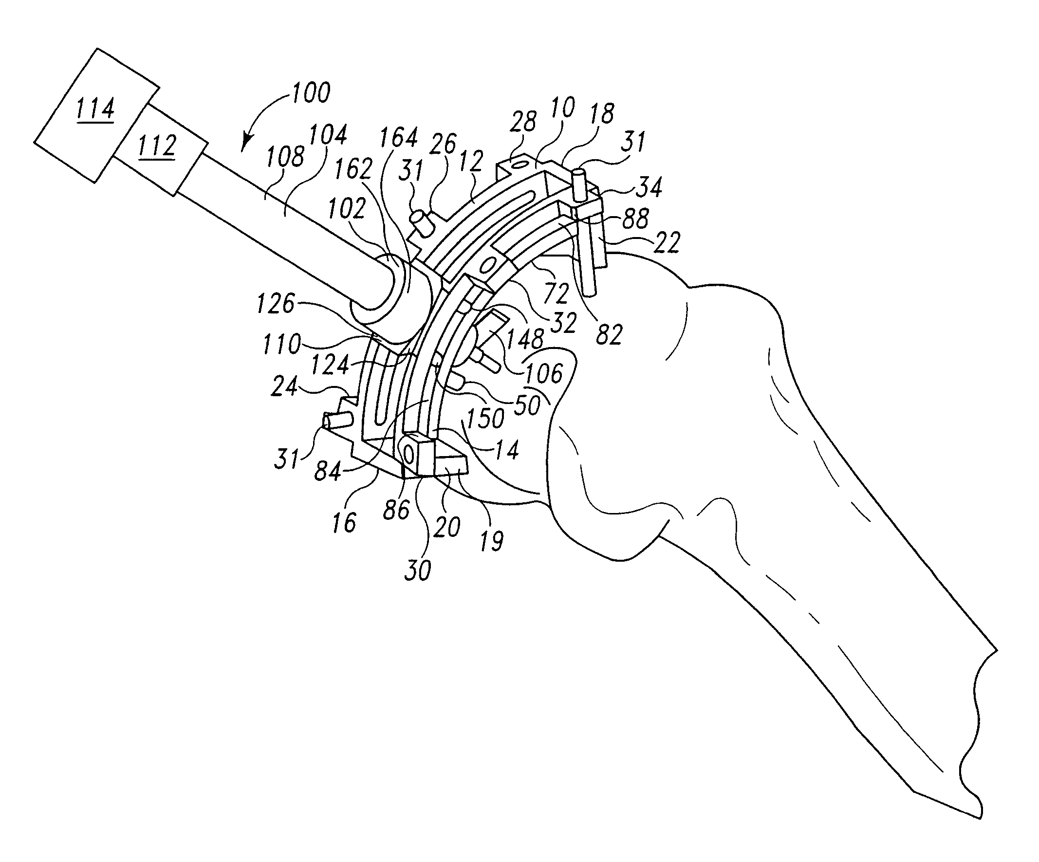
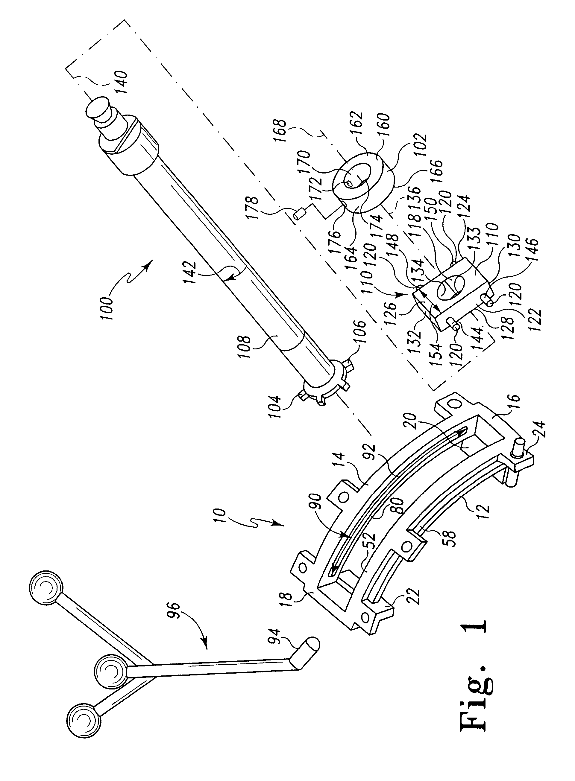
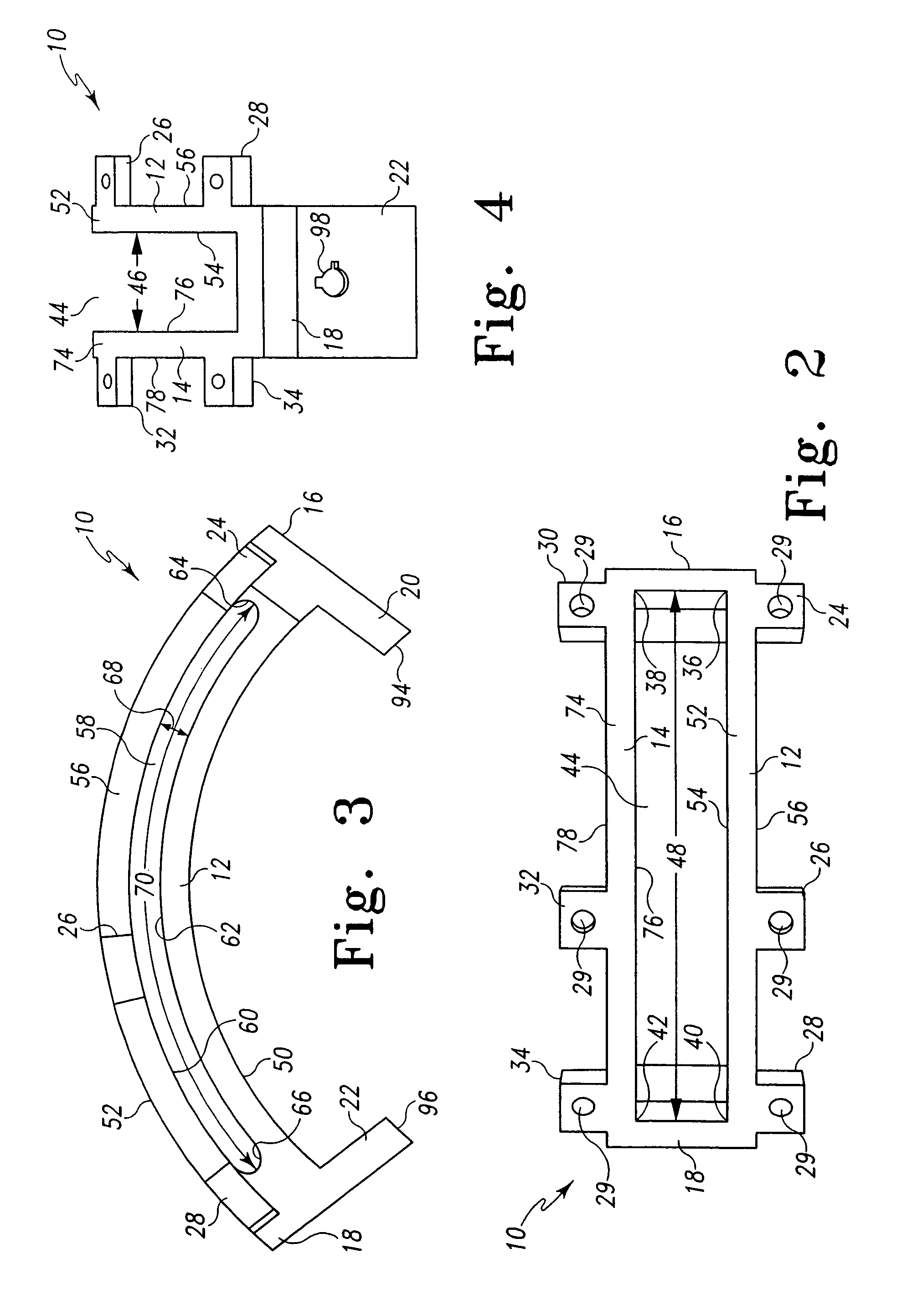
[0039]As shown, for example, generally in FIGS. 1-11 and more particularly in FIGS. 1-4, the guide 10 includes a medial rail 12, a lateral rail 14, a posterior cross member 16, an anterior cross member 18, a posterior leg 19, an anterior leg 21, and a plurality of ears 24, 26, 28, 30, 32 and 34. The posterior cross member 16 extends between and couples the posterior end 36 of the medial rail 12 and the posterior end 38 of the lateral rail 14. The anterior cross member 18 extends between and couples the anterior end 40 of the medial rail 12 and the anterior end 42 of the lateral rail 14. The medial rail 12, lateral rail 14, posterior cross member 16 and anterior cross member 18 cooperate to define a tool-receiving slot 44 through which portions of the cutting tools 100, 200 and / or drive shafts 112 of the power source 114 extend to drive the cutting tools 100, 200.

[0040]In the illustrated embodiment, the medial rail 12 and the lateral rail 14 extend longitudinally parallel to one anot...

second embodiment

[0060]As shown, for example, in FIGS. 5-7, a guided cutting tool 200 includes a posterior cutter 202, an anterior cutter 204, a posterior return spring 206, an anterior return spring 208, a driver 210, a plurality of pairs of shims 212 and a plurality of guide pins 214. The plurality of pairs of shims 212 are provided for placing under the anterior foot 22 and posterior foot 20 of the guide 10 for adjusting the effective length of the posterior leg 19 and the anterior leg 21 and, thus, the depth of the resection performed by the guided cutting tool 200. The plurality of pairs of shims 212 will be provided in pairs having incrementally differing thickness to facilitate incrementally increasing the depth of the resection by replacing the shims 212 after the posterior and anterior cutters 202, 204 cease removing bone from the femur.

[0061]The posterior cutter 202 includes a body 216 having a top wall 218, a cutting surface 220, a medial side wall 222, a lateral side wall 224, a posterio...


PUM


Abstract

A bone resection tool for resecting an end of a bone along a surface having a curvature comprises a guide, a cutting tool and a track follower. The guide is configured to be removably attached in a fixed position to the end of the bone. The guide is configured to include a track exhibiting a curvature generally corresponding to the curvature of the surface to be resected in the bone. The cutting tool includes a cutting face. The track follower is configured to couple to the cutting tool and cooperate with the track to facilitate reciprocation of the cutting tool relative to the guide to induce the cutting face to resect the bone along the surface having the curvature. A method for cutting a bone along a curved surface conforming to the curvature of a curved surface of the underside of a prosthetic component comprises the steps of incising the tissue surrounding the surface of the bone, positioning a guide alongside the surface of a bone to be cut, affixing the guide to the bone, interconnecting a cutter having a cutting face with the guide, maintaining the cutting face generally parallel to the tangent of the curved surface and traversing the cutting face along the bone while guiding the cutter along the track. The tissue incision incises the tissue surrounding the surface of the bone to be cut in a minimally invasive fashion. The positioned guide includes a track configured to assimilate the curvature of the curved surface of the underside of the prosthetic component.

Description

FIELD OF THE INVENTION[0001]This invention relates to joint arthroplasty and more particularly to tools and techniques for shaping a bone to receive a component of a joint replacement system.BACKGROUND AND SUMMARY[0002]It is well known to provide prosthetic joint components for replacing damaged and deteriorating joints. Typical joint replacements require resection of distal or proximal end of one or more of the bones forming the joint to be replaced to permit the prosthetic device to be firmly attached to the bone without altering the length of the limb in which the joint is being replaced. Joint component manufactures have recognized the benefits to be derived from joint replacement procedures that require less invasive surgeries with smaller incisions and more kinematically correct implants. Additionally, as younger patients are receiving joint replacements, there is a desire to provide joint replacements that allow the patient to recover from the replacement surgery more quickly...

Claims


Application Information

Patent Timeline
Patent Type & Authority Patents(United States)
IPC IPC(8): A61F5/00
CPCA61B17/1764A61B17/154
Inventor BENNETT, TRAVISWYSS, JOSEPH G.
Owner DEPUY PROD INC
Why Eureka
Try Eureka