Membrane filtration system

a filtration system and membrane technology, applied in the direction of membranes, multi-stage water/sewage treatment, separation processes, etc., can solve the problems of reducing the flow rate of concentrate, increasing power consumption, wasteful power consumption, etc., to prevent clogging of filtering membranes, and prevent wasteful power consumption

Active Publication Date: 2010-08-03
MIURA COMPANY LIMITED
View PDF9 Cites 7 Cited by
  • Summary
  • Abstract
  • Description
  • Claims
  • Application Information

AI Technical Summary

Benefits of technology

[0008]It is an object of the present invention to suppress wasteful power consumption in the feed pump for feeding water to the filtering membrane portion and to prevent clogging in the filtering membrane in the filtering membrane portion.
[0011]According to the first aspect of the invention, if the discharge flow rate of the concentrate from the filtering membrane portion increases or decreases, the return flow rate adjusting portion adjusts the return flow rate of the concentrate to the upstream side of the filtering membrane portion in correspondence therewith. In this way, the flow rate of the concentrate from the filtering membrane portion is maintained at the set value, thereby making it possible to maintain the proportion of the concentrate flow rate with respect to the flow rate of the product water. As a result, it is possible to prevent a wasteful power consumption in the feed pump for feeding water to the filtering membrane portion, and possible to maintain a fixed flow velocity at the surface of the filtering membrane, thereby preventing clogging in the filtering membrane due to fouling.
[0012]According to the second aspect of the invention, if the flow rate of the product water from the filtering membrane portion increases or decreases, the return flow rate adjusting portion adjusts the return flow rate of the concentrate to the upstream side of the filtering membrane portion in correspondence therewith. In this way, the proportion of the concentrate flow rate with respect to the flow rate of the product water can be maintained. As a result, it is possible to prevent a wasteful power consumption in the feed pump for feeding water to the filtering membrane portion, and possible to maintain a fixed flow velocity at the surface of the filtering membrane, thereby preventing clogging in the filtering membrane due to fouling.

Problems solved by technology

However, when the concentrate flow rate increases to a degree more than necessary with respect to the flow rate of the product water, the feeding flow rate of the feed pump also increases, resulting in an increase in power consumption.
As a result, the concentrate flow rate becomes higher than necessary as compared with the flow rate of the product water, and the feeding flow rate of the feed pump becomes higher than necessary, resulting in a wasteful power consumption.
As a result, as compared with the flow rate of the product water, the flow rate of the concentrate is reduced, and the flow velocity at the surface of the filtering membrane decreases, so there is a fear of generation of clogging in the filtering membrane due to fouling.
However, if, upon a reduction in the flow rate of the product water, the return flow rate of the concentrate remains the same, the flow rate of the concentrate becomes higher than necessary with respect to the flow rate of the product water, and the feeding flow rate of the feed pump becomes higher than necessary, resulting in a wasteful power consumption.
As a result, there is a fear of generation of clogging in the filtering membrane due to fouling.

Method used


Image

  • Membrane filtration system
  • Membrane filtration system
  • Membrane filtration system

Examples


first embodiment

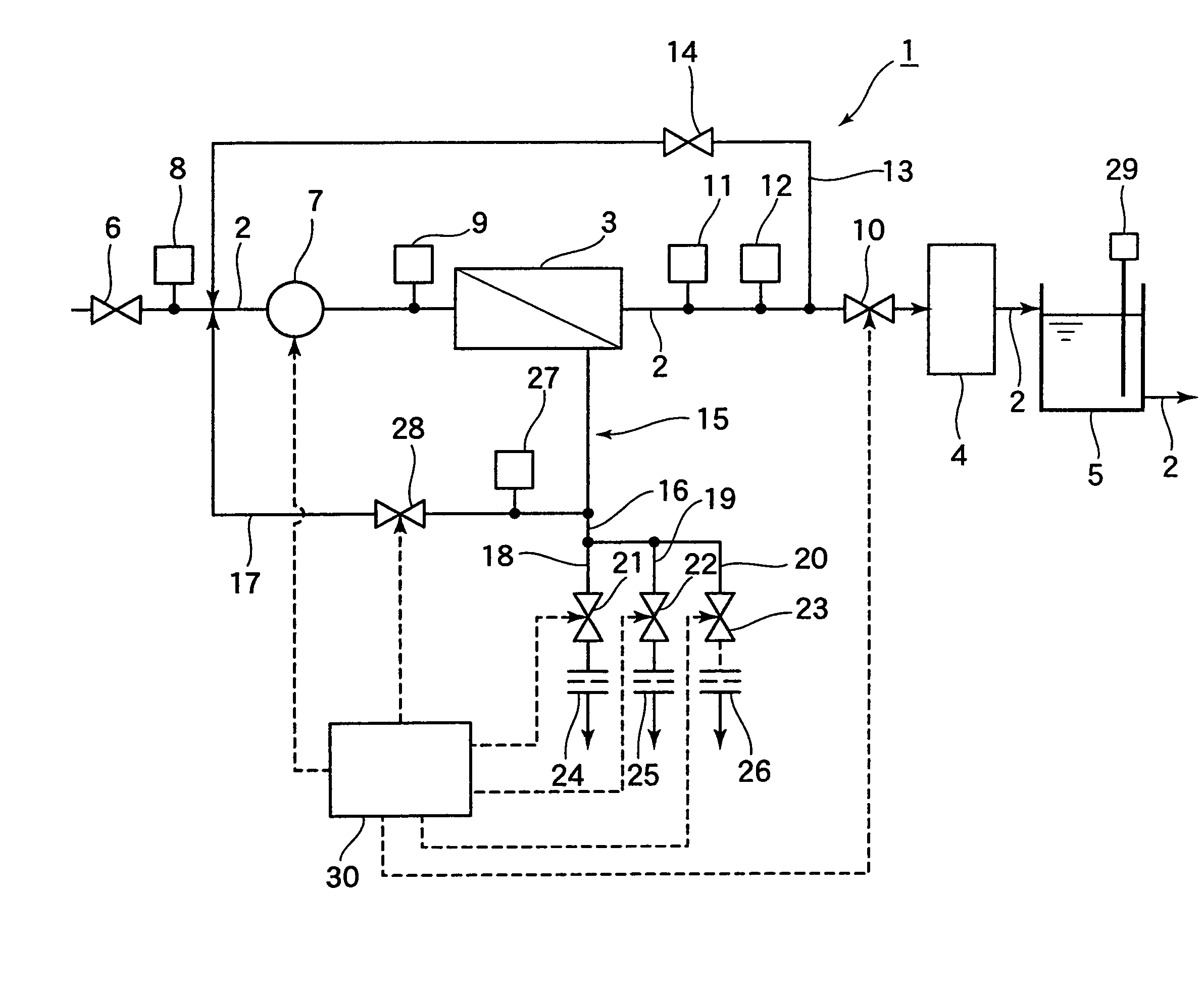
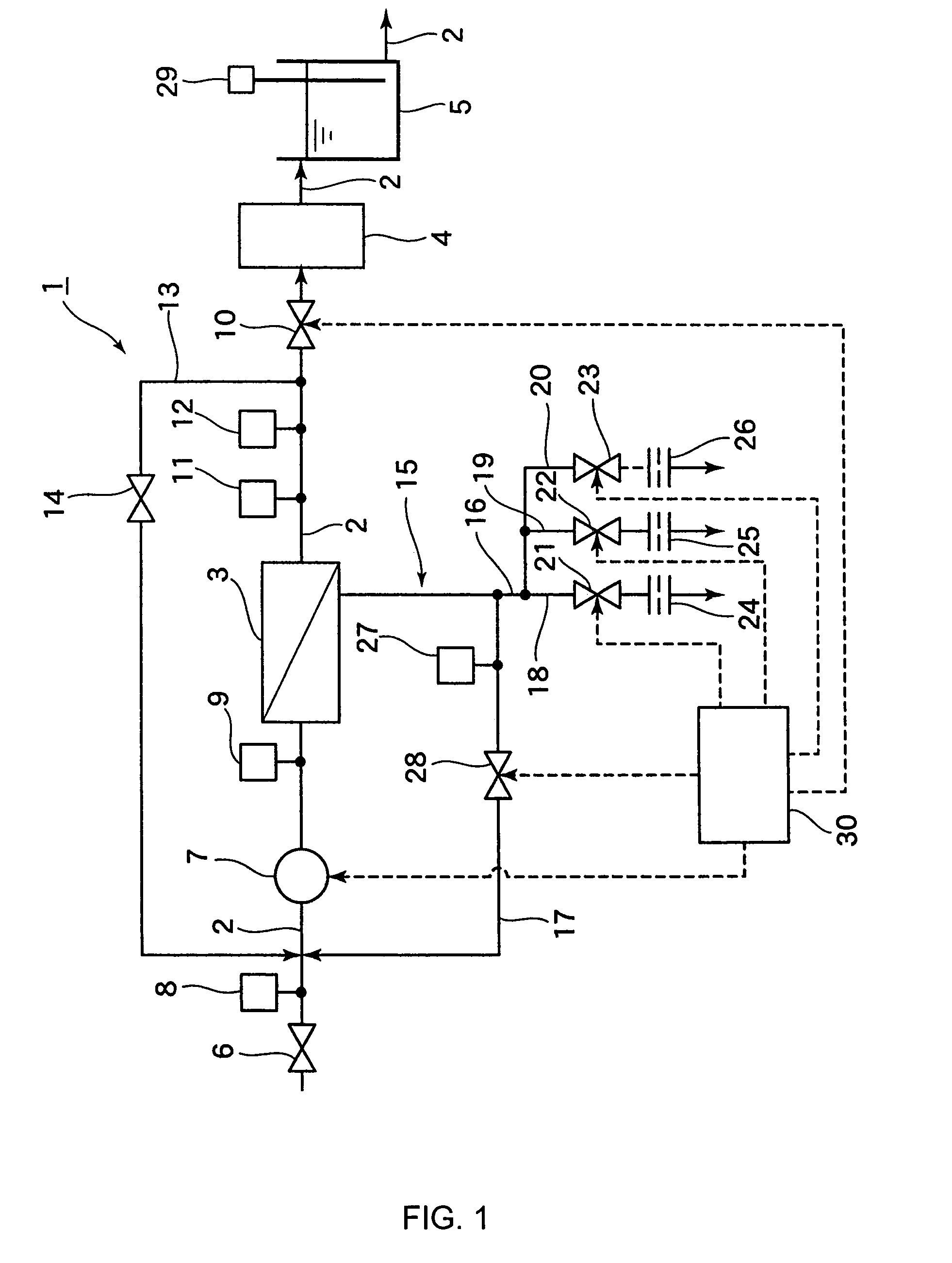
[0022]First, a first embodiment of the present invention will be described. In FIG. 1, a membrane filtration system 1 conducts treatment on raw water supplied from a raw water tank (not shown) storing raw water from a water source, such as city water, industrial water, or ground water, and this water is fed to an apparatus (not shown) such as a boiler, as feed water. The membrane filtration system 1 is equipped with a water supply line 2 for supplying water to the apparatus, and a filtering membrane portion 3 and a degassing membrane portion 4 which are connected to the water supply line 2, in the stated order from the upstream side. The product water that has passed through the filtering membrane portion 3 and the degassing membrane portion 4 is stored in a product water tank 5 connected to the water supply line 2.

[0023]The water supply line 2 has a first valve 6 and a feed pump 7 on the upstream side of the filtering membrane portion 3. The first valve 6 and the feed pump 7 are pr...

second embodiment

[0097]Next, a second embodiment of the present invention will be described with reference to FIG. 7. In FIG. 7, the same components as those of the membrane filtration system 1 of the first embodiment are indicated by the same reference numerals, and a detailed description thereof will be omitted.

[0098]In a membrane filtration system 40 shown in FIG. 7, the concentrate return line 17 branches off into a first concentrate return line 41, a second concentrate return line 42, and a third concentrate return line 43, and the concentrate return lines 41, 42, and 43 are provided with a fourth valve 44, a fifth valve 45, and a sixth valve 46 as return flow rate adjusting portion, respectively. Further, the concentrate return lines 41, 42, and 43 are provided with, on the downstream side of the valves 44, 45, and 46, a fourth constant flow rate valve 47, a fifth constant flow rate valve 48, and a sixth constant flow rate valve 49, respectively.

[0099]The valves 44, 45, and 46 are controlled b...


PUM

PropertyMeasurementUnit
pore sizeaaaaaaaaaa
temperatureaaaaaaaaaa

Abstract

The present invention provides a membrane filtration system (1) including: a filtering membrane portion (3) for removing impurities in feed water; a drain line (16) for draining a part of concentrate from the filtering membrane portion (3) to an exterior of a system; a concentrate return line (17) for returning a remainder of the concentrate from the filtering membrane portion (3) to an upstream side of the filtering membrane portion (3); a return flow rate adjusting portion (28) for concentrate provided in the concentrate return line (17); and a control portion (30) controlling the return flow rate adjusting portion (28) based on a drain flow rate of the concentrate or a flow rate of product water from the filtering membrane portion (3). With this construction, it is possible to suppress wasteful power consumption in a feed pump (7) for feeding water to the filtering membrane portion (3) and to prevent clogging in the filtering membrane in the filtering membrane portion (3).

Description

BACKGROUND OF THE INVENTION[0001]1. Field of the Invention[0002]The present invention relates to a membrane filtration system which is equipped with a filtering membrane portion for removing impurities in feed water and which returns a part of concentrate from the filtering membrane portion to an upstream side of the filtering membrane portion and discharges a remainder of the concentrate.[0003]2. Description of the Related Art[0004]As disclosed in JP 05-220480 A, as a water treatment system for feed water to an apparatus, a membrane filtration system is available which has a filtering membrane portion for filtering impurities contained in feed water, such as dissolved salts. In this membrane filtration system, feed water from a feed pump flows into the filtering membrane portion, and impurities contained in the feed water are filtered out. Then, permeate flowing out of the filtering membrane portion is supplied to the apparatus.[0005]Apart from the permeate, concentrate flows out o...

Claims


Application Information

Patent Timeline
Patent Type & Authority Patents(United States)
IPC IPC(8): B01D63/00C02F1/44C02F9/00
CPCB01D61/025B01D61/12B01D65/08C02F1/441B01D2313/12B01D2321/02C02F2209/40C02F2209/005C02F2209/02C02F2209/03B01D2321/10B01D63/00B01D61/00
Inventor YONEDA, TSUYOSHIMANABE, ATSUYUKI
Owner MIURA COMPANY LIMITED
Why Eureka
Try Eureka