Ignition apparatus for an internal-combustion engine

a technology of internal combustion engine and ignition apparatus, which is applied in the direction of electric ignition installation, mechanical equipment, machines/engines, etc., can solve the problems of easy blowout of spark discharge, increased wear on electrodes of spark plugs, and increased power consumption, so as to reduce electrode wear, increase ignitability, and suppress wasteful power consumption

Active Publication Date: 2017-02-02
DENSO CORP
View PDF0 Cites 6 Cited by
  • Summary
  • Abstract
  • Description
  • Claims
  • Application Information

AI Technical Summary

Benefits of technology

[0012]One embodiment provides an ignition apparatus for an internal-combustion engine which can reduce wear on electrodes of a spark plug and can suppress wasteful power consumption to increase ignitability.

Problems solved by technology

However, these ignition techniques have problems that wear on electrodes of a spark plug increases due to repeated re-discharge, and that power is wastefully consumed.
As a result, blowout of the spark discharge easily occurs due to a rotational flow or the like generated in a cylinder.
As a result, the ignition apparatus becomes large in size, and increase in cost is caused.

Method used


Image

  • Ignition apparatus for an internal-combustion engine
  • Ignition apparatus for an internal-combustion engine
  • Ignition apparatus for an internal-combustion engine

Examples


first embodiment

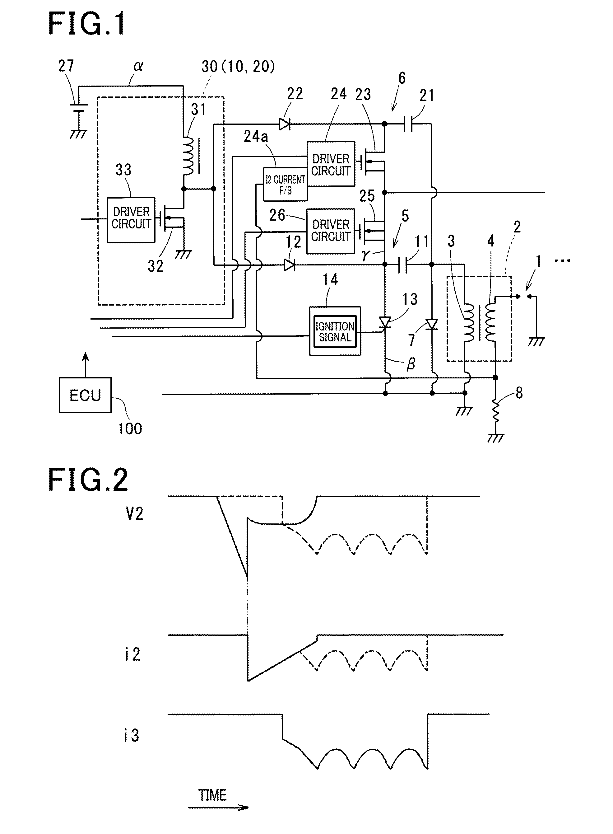
[0024]The first embodiment will be described with reference to FIGS. 1 to 5.

[0025]An ignition apparatus according to the first embodiment is mounted in a spark-ignition engine for vehicle traveling, and ignites (fires) an air-fuel mixture in a combustion chamber at predetermined ignition timing (ignition time). Note that an example of the engine is a direct injection type engine, which can perform lean combustion (lean burn combustion) using gasoline as fuel. In this engine, an EGR unit is mounted which returns part of exhaust gas as EGR gas to the engine intake side. In addition, the engine includes a rotational flow control section (rotational flow control means) that generates a rotational flow (tumble flow, swirl flow, or the like) of an air-fuel mixture in a cylinder.

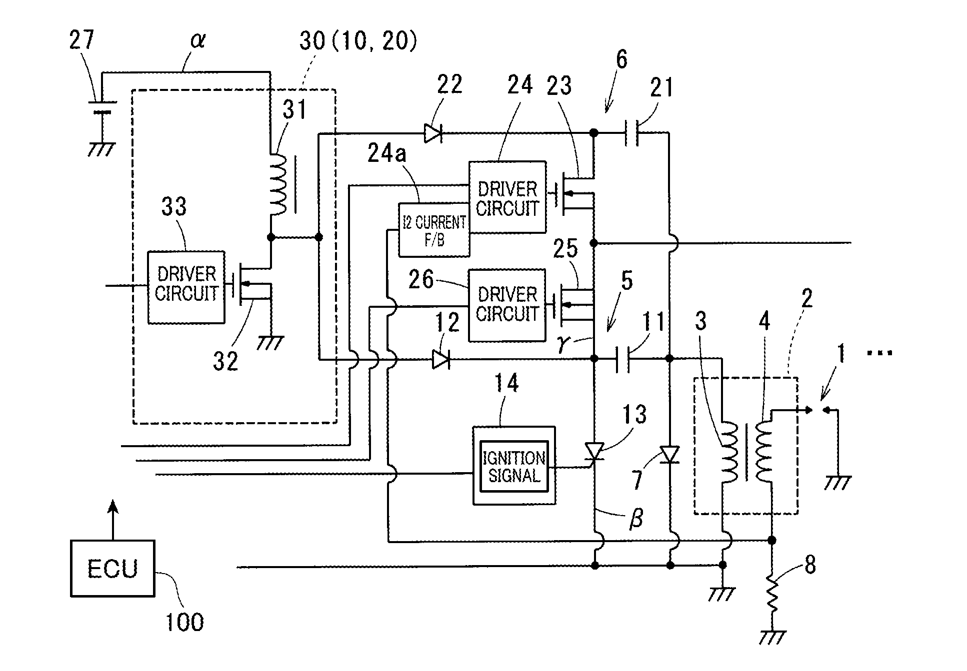
[0026]The ignition apparatus of the first embodiment is DI (direct ignition) type used for ignition coils 2 corresponding to respective spark plugs 1 of respective cylinders.

[0027]This ignition apparatus performs c...

second embodiment

[0090]The second embodiment will be described with reference to FIG. 6 and FIG. 7. Note that, in the following embodiments, the same reference numerals as those of the first embodiment indicate the same functional components.

[0091]In the second embodiment, as in the case of the first embodiment, the main ignition boosting circuit 10 and the energy input boosting circuit 20 are provided in common. In addition, in the second embodiment, the operation timing of the common boosting circuit is switched between (i) a main ignition charging time period X during which the main ignition capacitor 11 is charged and (ii) an energy input charging time period Y during which the energy input capacitor 21 is charged.

[0092]Specifically, the boosting circuit 30 is configured by including[0093]a first charging selection switching section (first charging selection switching means) 41 that turns on and off a charging line δ of the main ignition capacitor 11,[0094]a second charging selection switching s...

third embodiment

[0100]The third embodiment will be described with reference to FIG. 8.

[0101]In the third embodiment, the main ignition boosting circuit 10 and the energy input boosting circuit 20 are independently provided. Thereby, the charging voltage of the main ignition capacitor 11 and the charging voltage of the energy input capacitor 21 can be set to different values. As a result, each of the main ignition boosting circuit 10 and the energy input boosting circuit 20 can be specifically designed, whereby the ignition apparatus can decrease in size and in power consumption.

[0102]As a concrete example, 100 V or more of the charging voltage of the main ignition capacitor 11 is required to generate the main ignition (several tens kV or more of secondary voltage). Preferably, the charging voltage of the main ignition capacitor 11 is set to preferably 250 V or more. Meanwhile, 100 V or more of the charging voltage of the energy input capacitor 21 is required to generate the continuous spark dischar...


PUM

PropertyMeasurementUnit
charging voltageaaaaaaaaaa

Abstract

An ignition apparatus for an internal-combustion engine includes a main ignition CDI circuit that has a main ignition boosting circuit boosting battery voltage and a main ignition capacitor storing electric charge boosted by the main ignition boosting circuit, and that releases the electric charge stored in the main ignition capacitor to a primary coil of an ignition coil to make an ignition plug generate spark discharge, and an energy input circuit that has an energy input boosting circuit boosting battery voltage and an energy input capacitor storing electric charge boosted by the energy input boosting circuit, and that releases the electric charge stored in the energy input capacitor to the primary coil, during a spark discharge started by operation of the main ignition CDI circuit, to make a secondary current flow in the same direction and to a secondary coil of the ignition coil, thereby making spark discharge continue which is started by the operation of the main ignition CDI circuit.

Description

TECHNICAL FIELD[0001]The present invention relates to an ignition apparatus used for an internal-combustion engine (engine), in particular, to a technique for continuing spark discharge.BACKGROUND ART[0002]For ignition apparatuses, a technique for improving ignitability of an air-fuel mixture in an engine combustion chamber is preferable. As the technique for improving ignitability, there are known a powerful ignition technique for generating strong spark discharge by using a spark plug, and a multiple ignition technique for continuously generating strong spark discharge several times by using a spark plug.[0003]However, these ignition techniques have problems that wear on electrodes of a spark plug increases due to repeated re-discharge, and that power is wastefully consumed. Hence, an ignition apparatus is required which has high ignitability, and which can reduce wear on electrodes of a spark plug and can suppress wasteful power consumption.[0004]As a technique for increasing ign...

Claims


Application Information

Patent Timeline
Patent Type & Authority Applications(United States)
IPC IPC(8): F02P3/08H01F38/12
CPCH01F38/12F02P3/08F02P3/0892F02P9/007F02P15/10
Inventor TERADA, KANECHIYO
Owner DENSO CORP
Why Eureka
Try Eureka