Electromagnetic motor to create a desired low frequency vibration or to cancel an undesired low frequency vibration
a technology of electromagnetic motors and electromagnetic springs, applied in the direction of electrical equipment, mechanical energy handling, dynamo-electric machines, etc., can solve the problems of uneven spring load, frequent service, and application of this device in an audio system
- Summary
- Abstract
- Description
- Claims
- Application Information
AI Technical Summary
Problems solved by technology
Method used
Image
Examples
second embodiment
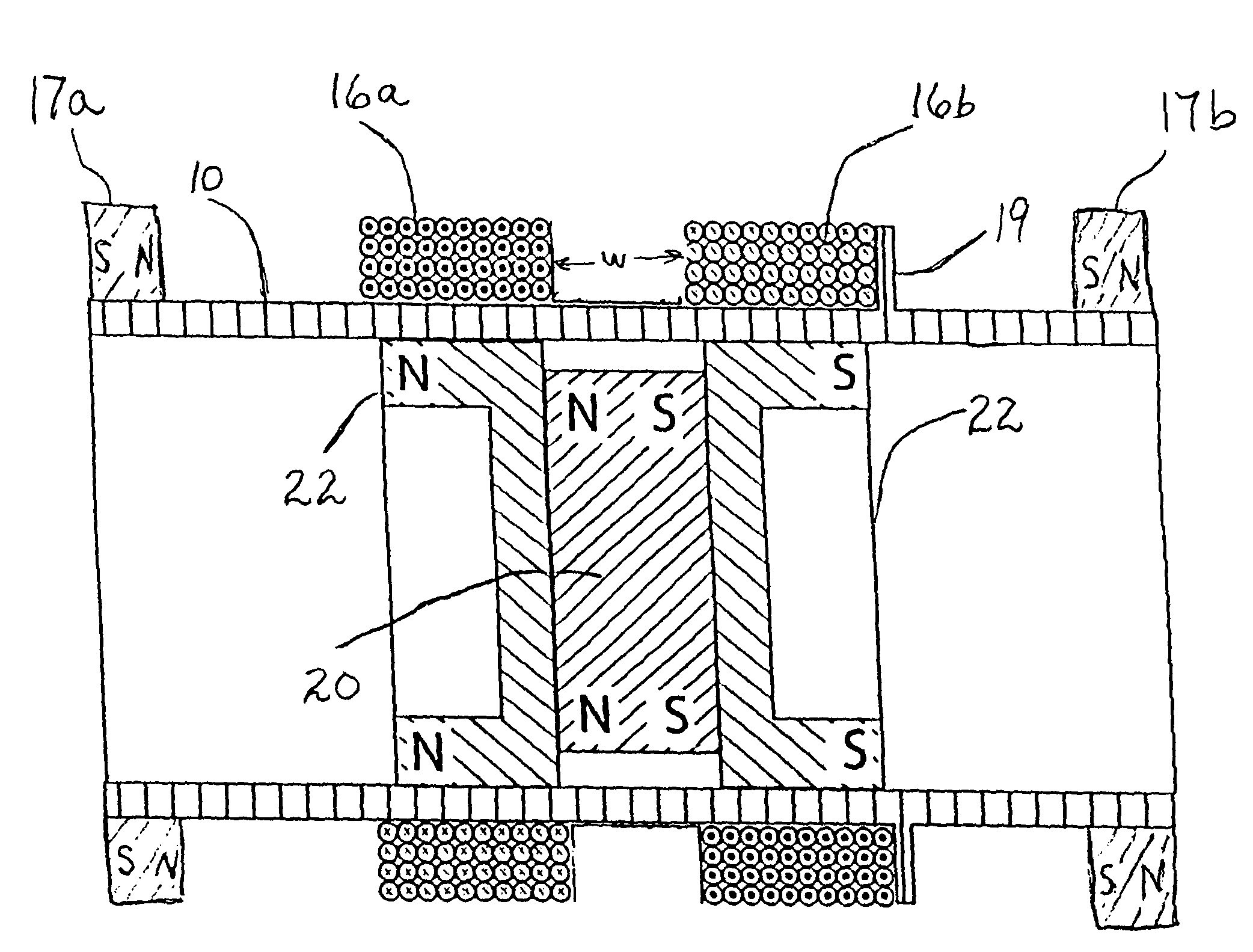
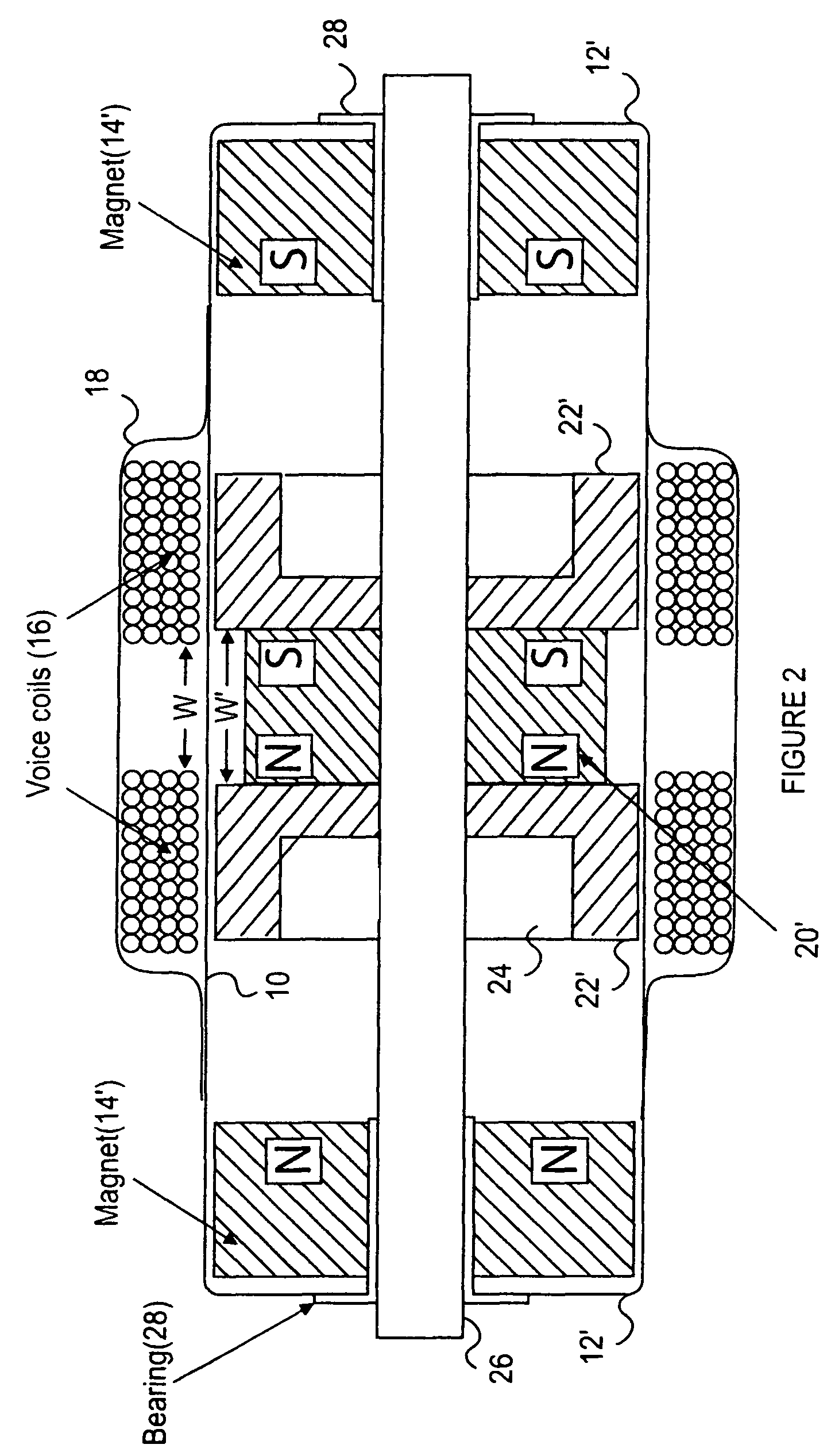
[0041]In FIG. 2 there is shown the present invention. This embodiment is similar to that of FIG. 1 and each of the items that are the same have the same reference number. Here each of the end caps 12′, end magnets 14′, slider magnet 20′ and plates 22′ have a hole through the longitudinal center. Passing through the hole in the center of each of those items is non-ferrous (non-magnetic) rod 26. Additionally there is a bearing in the center hole of end caps 12′ and magnets 14′ with rod 26 passing through bearings 28. The slider (magnet 20′ and plates 22′) is attached to rod 26. With rod 26 being centered and passing through the slider, the slider will always be centered in the diameter of tube 10 and thus be prevented from coming into contact with the inner surface of tube 10 when in motion or at rest.
[0042]The overall length of rod 26 depends on the width of slider magnet 20′ and the width of end magnets 12′. The minimum length of rod 26 must be greater than the distance between end ...
third embodiment
[0044]Referring next to FIG. 3 there is shown a longitudinal cross-section of the present invention. This embodiment is similar to that of FIG. 2 with the difference being that magnet 20′ and plates 22′ are not affixed to rod 26 and thus able to move on rod 26 when coils 16 are energized; while at the same time the ends of rod 26 are threaded with nuts 32 being tightened to contact each of end caps 12′. To reduce wear on non-ferrous rod 26 a bearing 30 can be added around rod 26 and extending into the center holes of magnet 20′ and plates 22′. In this configuration the result is the same regardless whether tube 10 is fastened to a fixed point external tube 10 or rod 26 is fastened to a fixed point external to tube 10 since nuts 32 prevent rod 26 from moving relative to tube 10. Therefore when coils 16 are energized only slider magnet 20′ and plates 22′, magnetically attached thereto, move relative to tube 10.
fourth embodiment
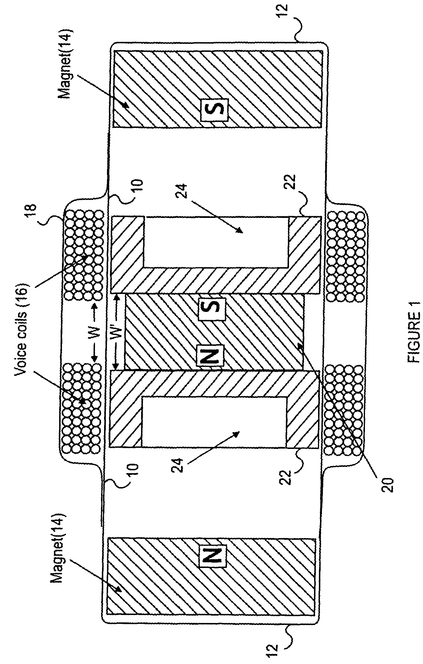
[0045]Next, turning to FIG. 4 there is shown a longitudinal cross-section of the present invention that is similar to the embodiment of FIG. 1 with several additions. Here, as has been done previously, the elements that are the same as those in FIG. 1 have been given the same reference numbers to avoid confusion.
[0046]One of the added features in this embodiment is the external treads 34 on the ends of tube 10 that mate with the internal treads 36 of end caps 12″. The inclusion of threads 34 and 36 permit a fine adjustment of the position of end caps 12″ and thus also end magnets 14 to equalize the magnetic strength exerted by each of end magnets 14 on the slider to accurately center the slider when at rest. Additionally, if the electromagnetic motor of the present invention is mounted vertically on one of end caps 12″ or at an angle with one of end caps 12″ lower than the other, the position of one or both end caps 12″ has / have to be adjusted to also adjust the magnetic forces to c...
PUM
 Abstract
Description
Claims
Application Information
 - R&D
- Intellectual Property
- Life Sciences
- Materials
- Tech Scout
- Unparalleled Data Quality
- Higher Quality Content
- 60% Fewer Hallucinations
Browse by: Latest US Patents, China's latest patents, Technical Efficacy Thesaurus, Application Domain, Technology Topic, Popular Technical Reports.
© 2025 PatSnap. All rights reserved.Legal|Privacy policy|Modern Slavery Act Transparency Statement|Sitemap|About US| Contact US: help@patsnap.com


