Cordless power tool

a power tool and cordless technology, applied in the field of cordless power tools, can solve the problems of large electric power required and the life of the protection unit is reduced, and achieve the effect of preventing erroneous operation and suppressing heat generation of the protection uni

Active Publication Date: 2010-08-03
KOKI HLDG CO LTD
View PDF7 Cites 16 Cited by
  • Summary
  • Abstract
  • Description
  • Claims
  • Application Information

AI Technical Summary

Benefits of technology

[0009]Therefore, an object of the invention is to provide a cordless power tool which can suppress heat generation of the protection unit and prevent the erroneous operation.MEANS FOR SOLVING THE PROBLEMS
[0013]According to the cordless power tool in the first aspect of the invention, the protection unit is arranged so that at least its part is located in the passage of the cool air. Therefore, it is possible to suppress heat generation of the protection unit and prevent erroneous operation. Further, it is possible to prevent the life of the protection unit from lowering.
[0014]According to the cordless power tool in the second aspect of the invention, the air window is formed in the body housing, and the protection unit is provided in the vicinity of the air window. Therefore, also in the motor stopping time, the protection unit is easy to come into contact with the outside air, so that the protection unit is difficult to receive an influence of heat generated by the motor.
[0015]According to the cordless power tool in the third aspect of the invention, the protection unit is provided in the position where it does not interrupt the passage of the cool air and in the position where its part protrudes in the passage of the cool air, whereby a part of the cool air introduced from the air window goes toward the protection unit and another part of the cool air goes directly to the motor. Accordingly, without interrupting the cool air flowing toward the motor, the protection unit can be cooled while keeping cooling performance of the motor.

Problems solved by technology

In order to operate such the power tool, large electric power is required.
However, when the power tool is operated with high load, the protection unit may generate heat and causes an erroneous operation due to an influence of the heat.
Further, there is fear that the life of the protection unit lowers.

Method used


Image

  • Cordless power tool
  • Cordless power tool
  • Cordless power tool

Examples


first embodiment

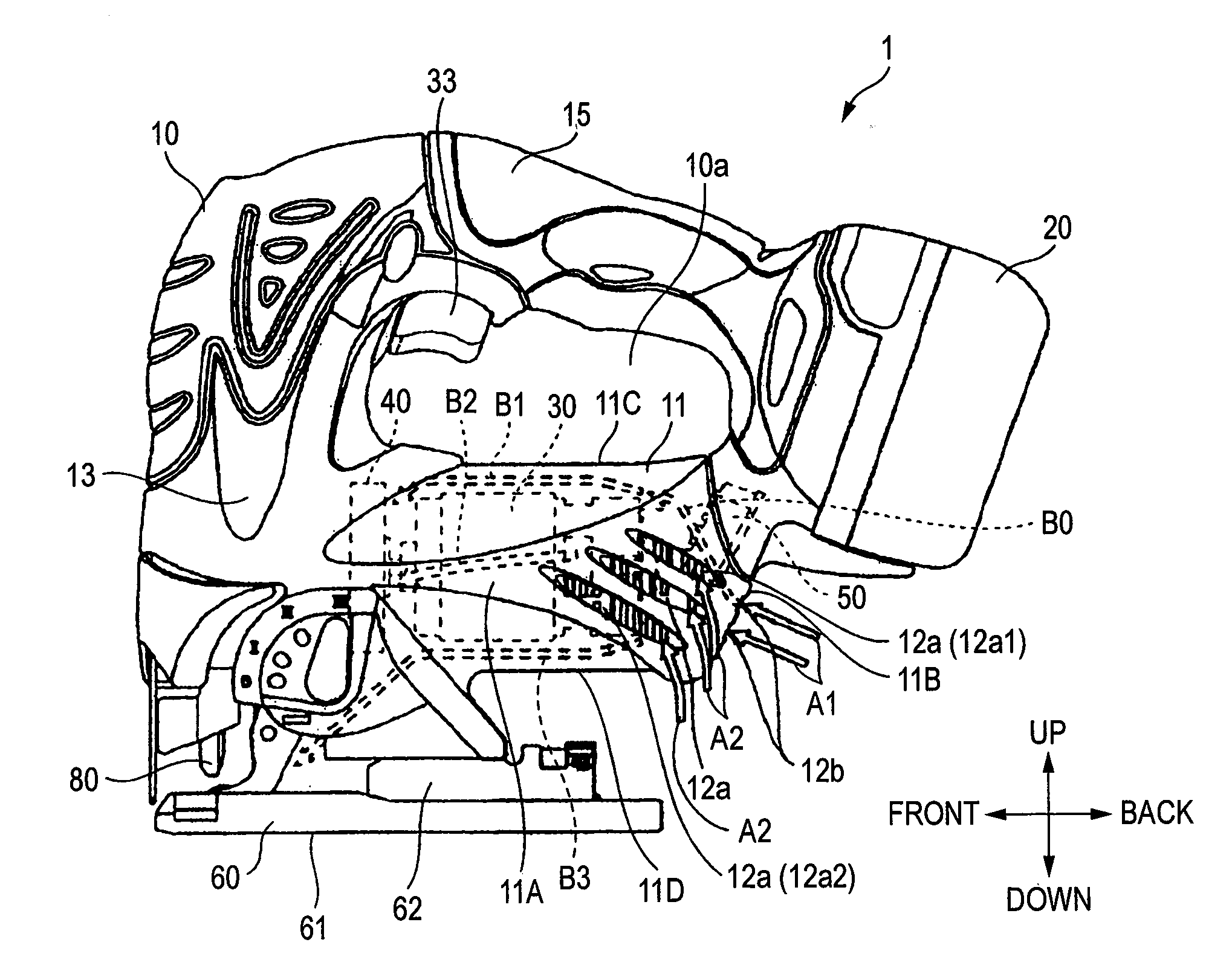
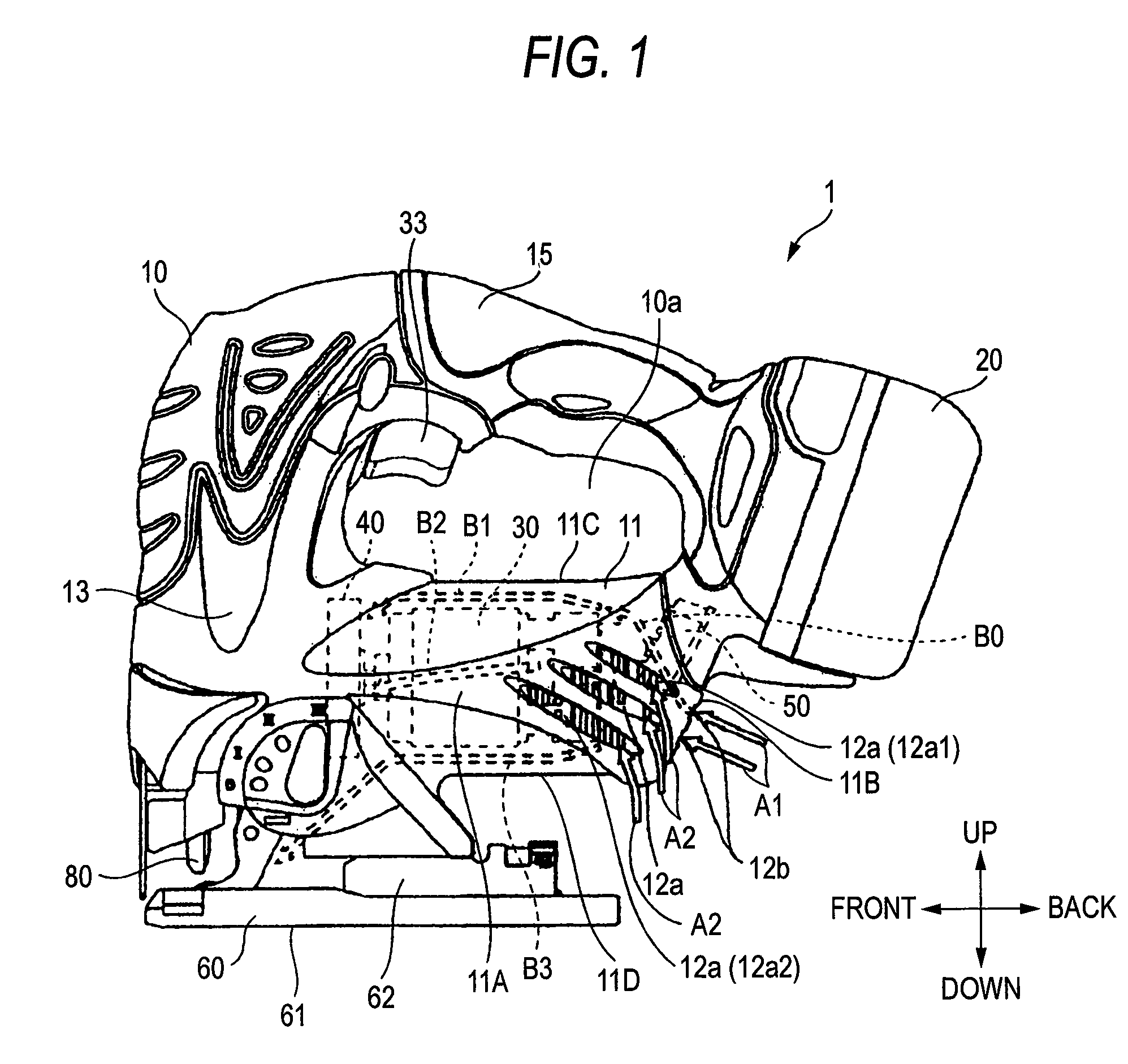
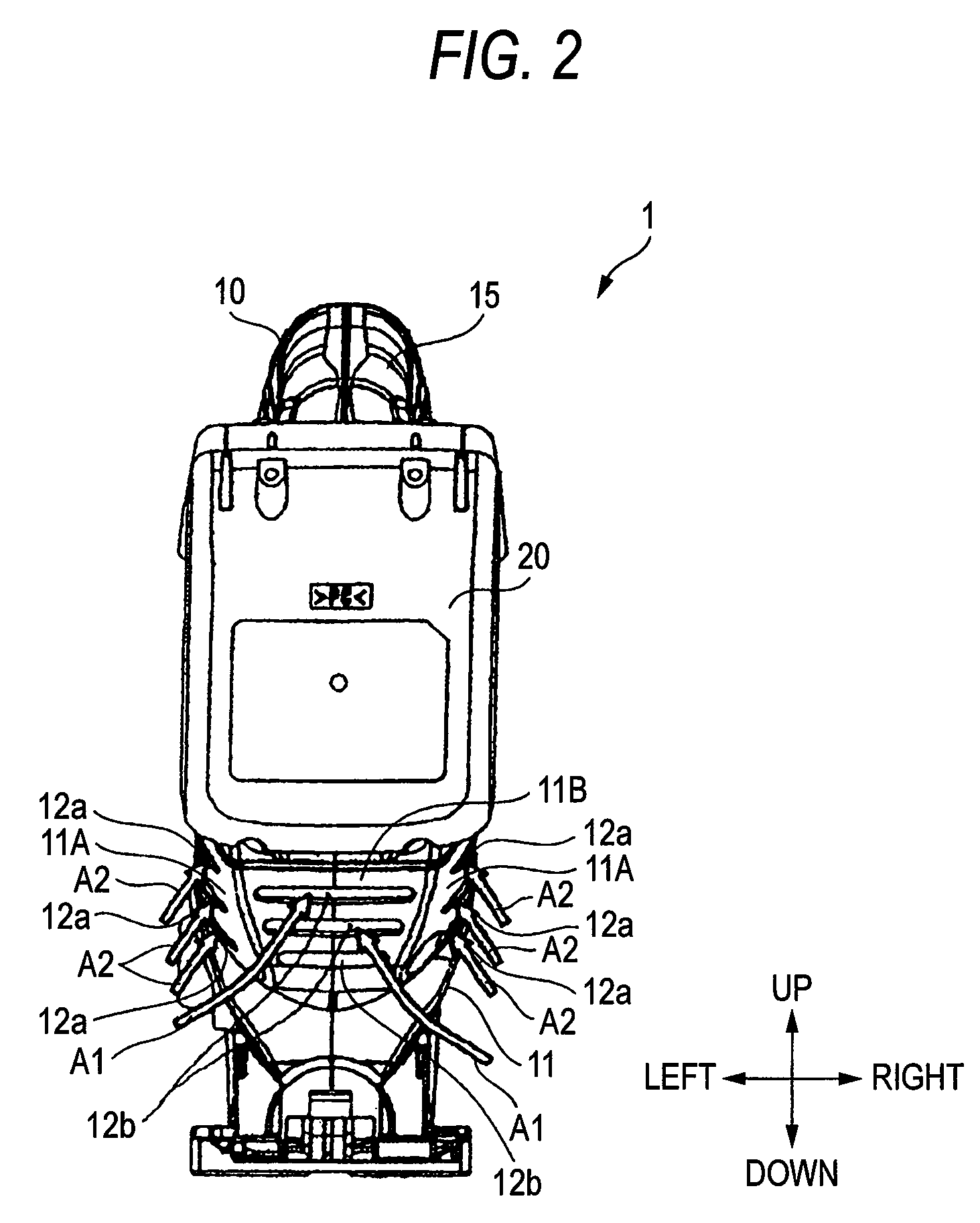
[0024]A cordless power tool according to the invention will be described with reference to FIGS. 1 to 4. A cordless power tool 1 according to the embodiment is a jigsaw. The cordless power tool 1 includes mainly a body casing 10, a battery pack 20, a motor 30, a cooling fan 40, a protection unit 50, a base part 60, a drive part 70 (FIG. 3), and a blade 80. For convenience of description, as shown in FIGS. 1 to 3, a direction of a rotation shaft of the motor 30 is taken as a front and back direction, and a direction which is orthogonal to the front and back direction and where the blade 80 extends is taken as a up-down direction. Further, a direction which is orthogonal to both of the front and back direction and the up-down direction is taken as a left and right direction (FIG. 2).

[0025]As shown in FIGS. 1 and 3, the body casing 10 is composed of a frame formed of aluminum, and includes a motor housing 11, a gear housing 13 and a handle 15. In the motor housing 11, a motor accommoda...

second embodiment

[0053]A cordless power tool according to the invention will be described with reference to FIG. 5. A cordless power tool 101 according to the embodiment is a stud cutter. The cordless power tool 101 includes a body casing 110, a battery pack 120, a motor and a cooling fan which are not shown, a protection unit 150, and a cutter part 180. In the cordless power tool 101, a full thread is arranged in the cutter part 180 in a predetermined state, and a cutting mechanism provided for the cutter part 180 is operated, whereby the full thread can be cut.

[0054]The body casing 110 has a motor housing 111 and a handle 115. Plural air windows 112a composed of slit-shaped opening portions are formed at the back portion from the motor (not shown) (in a position close to the battery pack 120), of a side wall 111A of the motor housing 111. Plural exhaust holes 112b composed of slit-shaped opening portions are formed in the front portion from the motor (not shown), of the side wall 111A. Further, be...

third embodiment

[0057]A cordless power tool according to the invention will be described with reference to FIG. 6. A codeless power tool 201 according to the embodiment is a grinder. The cordless power tool 201 includes a body casing 210, a battery pack 220, a motor and a cooling fan which are not shown, a protection unit 250, and a grindstone 280. The cordless power tool 201 is a tool for grinding a material to be ground by rotating the grindstone 280 by the drive force of the motor.

[0058]The body casing 210 has a motor housing 211. In the cordless power tool 201 according to this embodiment, the motor housing 211 is used also as a handle which is a portion gripped by a user. Plural air windows 212a composed of slit-shaped opening portions are formed at the back portion from the motor (not shown) (in a position close to the battery pack 220), of a side wall 211A of the motor housing 211. Plural exhaust holes (not shown) composed of slit-shaped opening portions are formed in a front wall 211B of th...


PUM


Abstract

To provide a cordless power tool which can suppress heat generation of a protection unit and prevent the erroneous operation. A cordless power tool 1 includes a body casing 10; a battery 20 which is detachably attached to the body casing 10 and can supply electric power; a motor 30 which is housed in the body casing 10, and generates rotation force by the electric power of the battery 20; a cooling fan 40 which rotates by the rotation force of the motor 30; and a protection unit 50 which shuts off the power supply to the motor 30, in accordance with a detection result of the state of the battery 20, so that the battery 20 does not enter an overdischarge state or an overcurrent state. Herein, a passage of cool air generated by the cooling fan 40 is formed in the body casing 10, and the 16 protection unit 50 is arranged so that at least its part is located in the passage of the cool air.

Description

CROSS-REFERENCE TO RELATED APPLICATIONS[0001]This application is based on and claims the benefit of priority from the prior Japanese Patent Application No. 2007-008695, filed on Jan. 18, 2007; the entire contents of which are incorporated herein by reference.BACKGROUND OF THE INVENTION[0002]1. Technical Field[0003]The present invention relates to a cordless power tool.[0004]2. Background Art[0005]Heretofore, there has been known a cordless power tool (hereinafter referred to as a power tool) which operates upon reception of power supply from a battery pack attached detachably to a main body, such as a jig saw, a stud cutter, or the like. In order to operate such the power tool, large electric power is required. Therefore, in addition to a Ni—Cd battery and a nickel-hydride battery, recently, a lithium-ion battery is widely used as a rechargeable battery of a battery pack.[0006]There is an advantage that the lithium-ion battery can supply large electric power and realize size / weight ...

Claims


Application Information

Patent Timeline
Patent Type & Authority Patents(United States)
IPC IPC(8): H02H7/08
CPCB25F5/00B25F5/008
Inventor UCHIDA, HIROKI
Owner KOKI HLDG CO LTD
Why Eureka
Try Eureka