Vibrating debris remover

a technology of vibrating debris and remover, which is applied in the direction of mechanical vibration separation, vehicle cleaning, instruments, etc., can solve the problems of significant time it takes to remove debris, obstructed field of view with metal wire technology, and significant problem of debris, etc., to achieve efficient propagation of mechanical motion or vibration

Inactive Publication Date: 2010-08-10
LUDWICZAK DAMIAN R
View PDF44 Cites 11 Cited by
  • Summary
  • Abstract
  • Description
  • Claims
  • Application Information

AI Technical Summary

Benefits of technology

[0008]One embodiment of the present invention may comprise a device having two elements, a converter sub-unit and an amplifying coupler sub-unit. These two elements may used together to efficiently propagate mechanical motion or vibrations into, for example, an edge of a material, causing the material to vibrate. Because the material may vibrate with sufficient displacement and acceleration, the removal of the debris is achieved by breaking the adhesive bond existing between the material and the undesired debris. This may be done without harming the material and without obstructing the view through the material.

Problems solved by technology

The accumulation of this debris poses a significant problem with maintaining a clear view to the outside environment.
A major drawback to these devices is that the time it takes to remove the debris is significant.
Also, the field of view is obstructed with the metal wire technology.
A major drawback of these devices is that the vibrating transducer elements mount perpendicular and directly on the material surface.
Because the vibrating transducer elements are attached in this manner, the magnitude of the vibrations developed by the transducer elements cannot be altered, and in particular magnified, prior to entering into the material.
This results in a design which is very inefficient because of the amount of energy required to generate the necessary vibration amplitude in the material to remove the unwanted debris.
Another drawback of these devices is that the dimensions of the vibrating transducer piezoelectric or magnetostrictive elements have to be carefully chosen such that their natural vibration frequency is tuned to that of the material in order that the device works efficiently.
Additionally, some of the above referenced devices are mounted on the material surface in such a way that the field of view through the material can be highly obstructed if applied in the use of windshield or side windows for removing debris.

Method used


Image

  • Vibrating debris remover
  • Vibrating debris remover
  • Vibrating debris remover

Examples


Embodiment Construction

[0042]The concern for the removal of debris from a material is very real. The present invention shall be described with respect to an automotive windshield. However, this should in no way be restrictive, as a great many other materials and applications exist to which this invented debris removal device could be employed.

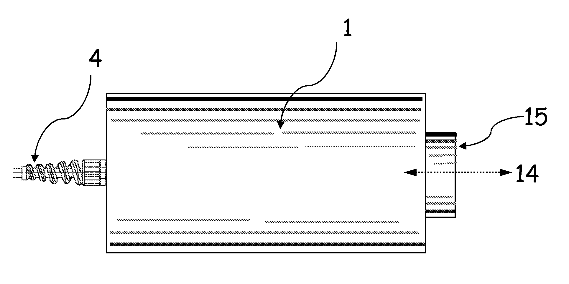
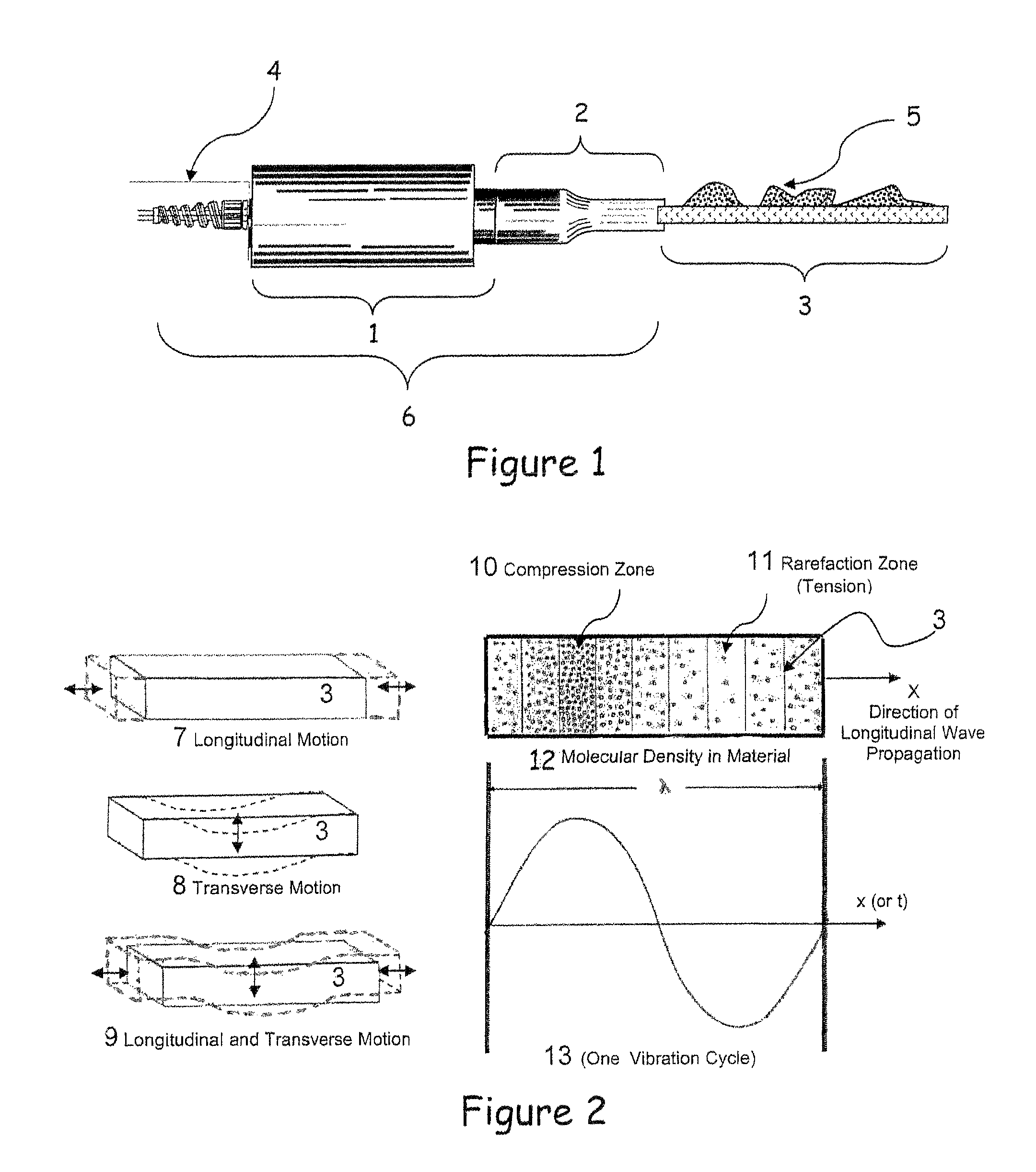
[0043]As shown in FIG. 1, some type of debris 5, such as ice and or water, can build on a material 3 surface, such as an automobile windshield, to a level where visibility to the outside environment is impaired. This results in a dangerous operating condition. A vibrating debris remover 6 has been invented that can remove debris 5, such as ice, from a material 3 surface, such as an automotive windshield 40 or aircraft airframe 43. The vibrating debris remover 6 consists of two parts, the converter sub-unit 1 and the amplifying coupler sub-unit 2 to which the material 3 is attached.

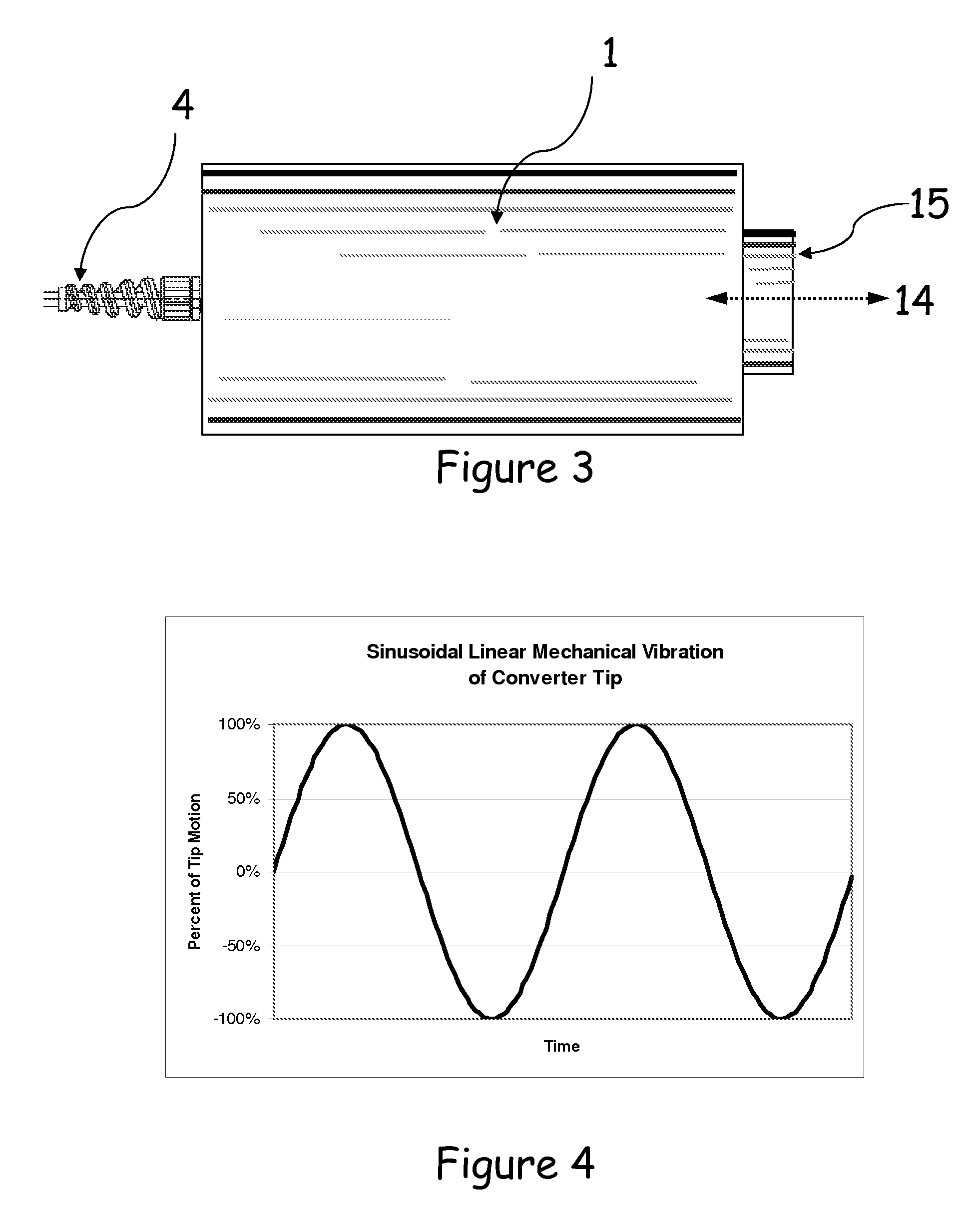
[0044]The converter sub-unit 1 and amplifying coupler sub-unit 2 are so arranged as to ...


PUM

PropertyMeasurementUnit
electrical energyaaaaaaaaaa
time delayaaaaaaaaaa
frequencyaaaaaaaaaa

Abstract

Embodiments of the present invention relate to a device which may be permanently attached or removably attached to a material such as a vehicular glass window or airplane wing. This device may comprise of a converter sub-unit or vibrator and a coupler. These elements may be arranged to propagate mechanical motion generated by the converter sub-unit through the coupler and optionally into the edge of the attached material. The resulting vibration motion in the material, which could take the form of a longitudinal compression / rarefaction wave, transverse wave, or a combination of the two waveforms, may be of a sufficient magnitude so as to cause the adhesive bond between the material's surface and other solid debris, such as ice, to be broken. This allows the debris to fall away while not damaging the material. The vibration motion in the material may be also of sufficient magnitude to remove a liquid such as water from the material surface. In other embodiments, the device is connected to a pulser / receiver and / or a frequency spectrum electronic unit to function as a debris detector.

Description

[0001]This application is a Continuation-in-Part of U.S. application Ser. No. 11 / 461,667, filed Aug. 1, 2006 and entitled “Vibrating Debris Remover, which is a Continuation of U.S. application Ser. No. 10 / 949,613, entitled “Vibrating Debris Remover,” now U.S. Pat. No. 7,084,553, which claims the benefit of U.S. Provisional Application Ser. No. 60 / 550,567, filed Mar. 4, 2004, all of which are hereby incorporated herein by reference.GOVERNMENT INTEREST[0002]This invention was made by an employee of the Untied States Government. The Government has a nonexclusive, irrevocable, royalty-free license in the invention with power to grant licenses for all governmental purposes.TECHNICAL FIELD[0003]This invention relates to a device that when attached along the edge of a material, such as a vehicular window, will propagate mechanical vibration or shock motion created by the device into the material with sufficient magnitude in order to remove solid debris, such as ice, and / or liquid debris, s...

Claims


Application Information

Patent Timeline
Patent Type & Authority Patents(United States)
IPC IPC(8): G01N29/07H02N2/00G01N29/12
CPCB06B3/00B08B7/028B60S1/02B64D15/163G01N29/07G01N29/4427G01N29/46G01N2291/2694
Inventor LUDWICZAK, DAMIAN R.
Owner LUDWICZAK DAMIAN R
Why Eureka
Try Eureka