Miter saw having compact gear case at cutting portion

a technology of compact gear case and miter saw, which is applied in the field of miter saw, can solve the problems of interference between the cutting portion and the workpiece, low cutting performance, and inability to easily achieve bevel cutting to a thick workpiece, and achieve the effect of avoiding mechanical interferen

Inactive Publication Date: 2010-08-10
KOKI HLDG CO LTD
View PDF6 Cites 4 Cited by
  • Summary
  • Abstract
  • Description
  • Claims
  • Application Information

AI Technical Summary

Benefits of technology

[0006]It is therefore an object of the present invention is to provide a miter saw capable of avoiding mechanical interference between the cutting portion and a workpiece.

Problems solved by technology

Since the power transmission mechanism is disposed nearby a rotation shaft of the circular saw blade, a portion of the cutting portion surrounding the power transmission mechanism may abut against the workpiece during cutting operation, to lower cutting performance.
Therefore, bevel cutting to a thick workpiece my not be easily achievable.
However, there is still a problem of interference between the cutting portion and the workpiece in the disclosed miter saw when the cutting portion is laterally tilted in a direction coincident with a projecting direction of the power transmission mechanism from one lateral side of the cutting portion in comparison with a case when the cutting portion is tilted in an opposite lateral direction opposite to the projecting direction of the power transmission mechanism.
Further, the bevel cutting when the cutting portion is laterally tilted in the direction coincident with the projecting direction of the power transmission mechanism cannot be performed with respect to a specific standardized member.

Method used


Image

  • Miter saw having compact gear case at cutting portion
  • Miter saw having compact gear case at cutting portion
  • Miter saw having compact gear case at cutting portion

Examples


Embodiment Construction

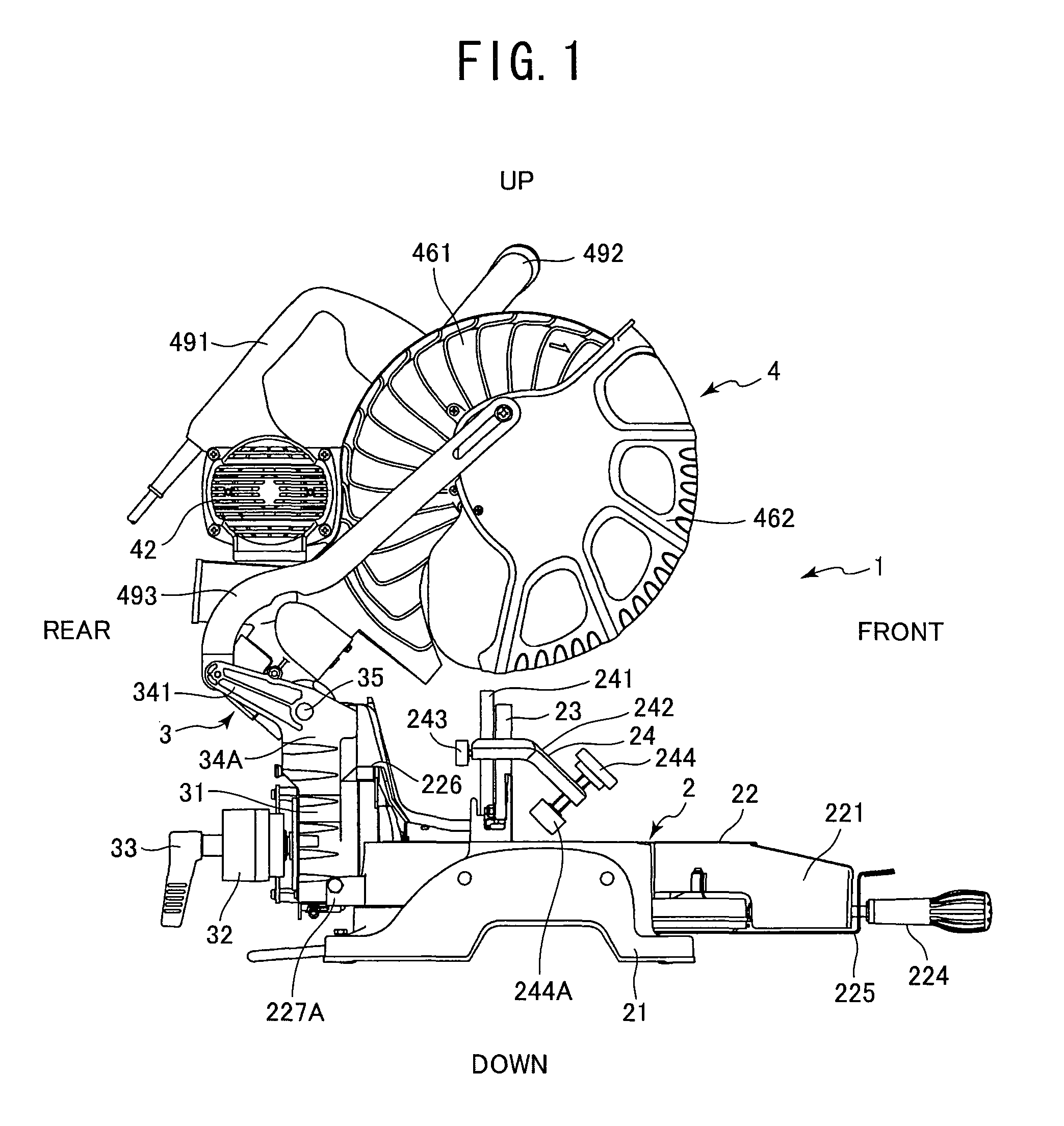
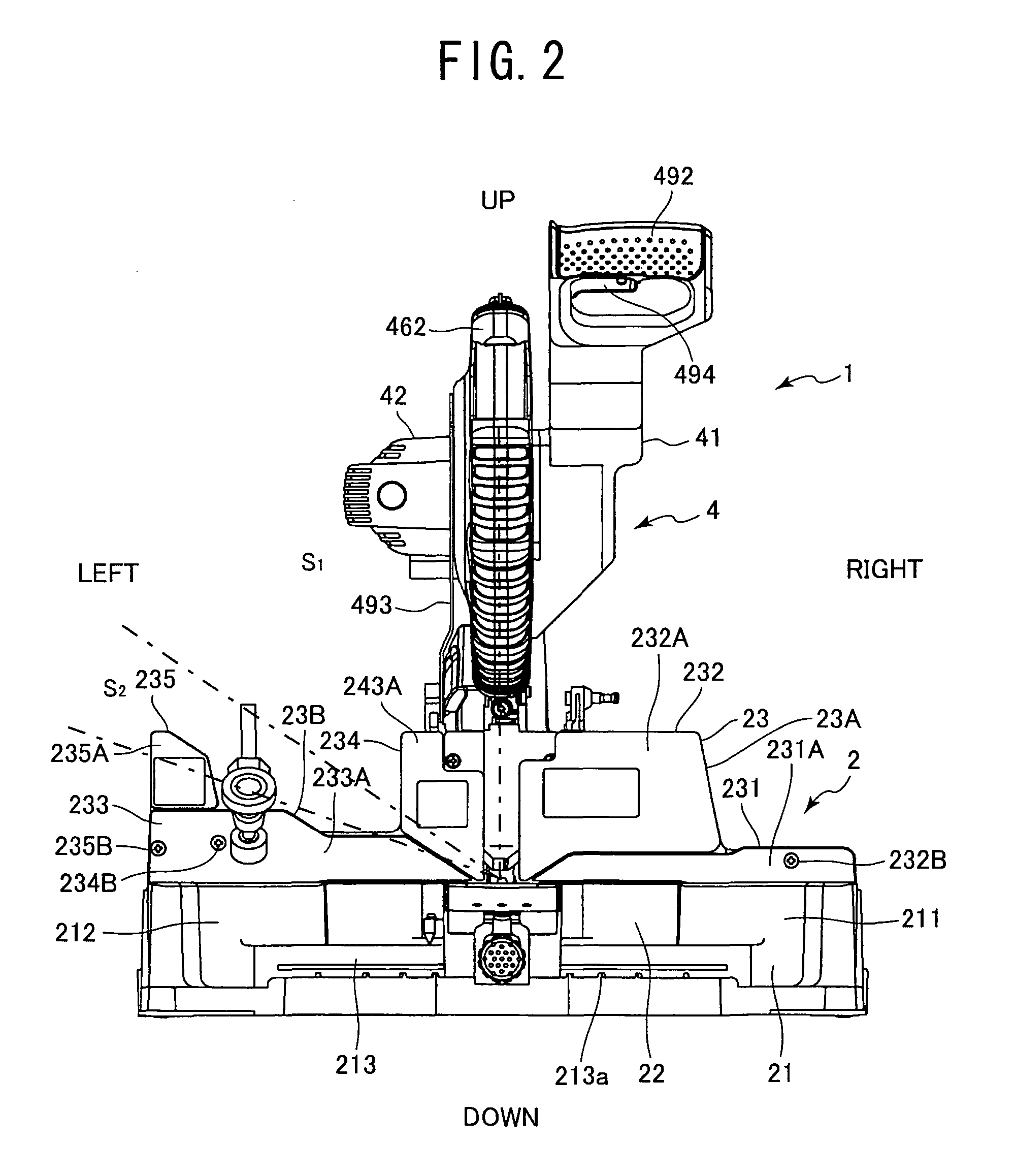
[0036]A miter saw according to a first embodiment of the present invention will be described with reference to FIGS. 1 through 20. As shown in FIGS. 1 and 2, the miter saw 1 includes a base portion 2 installed on a floor or a table stand for mounting a workpiece such as a wood block, a cutting portion 4 for cutting the workpiece, and a support portion 3 for pivotally movably and laterally tiltably supporting the cutting portion to the base portion 2.

[0037]As shown in FIGS. 1 and 2, the base portion 2 includes a base 21, a turntable 22 rotatable about its axis relative to the base 21, and a fence 23 having a support surface to which a side surface of the workpiece is abuttable at a position above the base 21 for positioning the workpiece. In the following description, the supporting surface side of the fence 23 is defined as the front side, the extending direction of the fence 23 is defined as leftward / rightward or lateral direction, and a ground side of the base 21 is defined as a l...


PUM

PropertyMeasurementUnit
anglesaaaaaaaaaa
anglesaaaaaaaaaa
anglesaaaaaaaaaa

Abstract

A miter saw having a cutting portion movable toward and away from a base and laterally tiltable for bevel cutting. A gear case is provided at the cutting portion and is positioned at one lateral side of the cutting portion. A bearing holder is provided in the gear case for holding a bearing which rotatably supports a spindle for a circular saw blade. The bearing holder has a thickness smaller than an axial length of the bearing. A first bearing nip member in contact with one axial end of the bearing is fixed to one side of the bearing holder, and a second bearing nip member in contact with another axial end of the bearing is fixed to another side of the bearing holder. These nip members are made from a material having a mechanical strength higher than that of the bearing holder.

Description

BACKGROUND OF THE INVENTION[0001]The present invention relates to a miter saw, and more particularly, to a miter saw having a compact gear case at a cutting portion.[0002]In a miter saw having a cutting portion provided with a circular saw blade, cutting operation is performed by pivotally moving the cutting portion toward and away from a base portion on which a workpiece is mounted. A power transmission mechanism is provided in the cutting portion for rotating the circular saw blade. The mechanism includes an output shaft fixing the circular saw blade, and gears and pulleys those drivingly connecting the output shaft to a power source such as a motor. Since the power transmission mechanism is disposed nearby a rotation shaft of the circular saw blade, a portion of the cutting portion surrounding the power transmission mechanism may abut against the workpiece during cutting operation, to lower cutting performance.[0003]In a recent miter saw, a bevel cutting at an acute angle between...

Claims


Application Information

Patent Timeline
Patent Type & Authority Patents(United States)
IPC IPC(8): B23D45/04
CPCB23D45/044B23D47/12B27B5/29B27B5/30B27B27/08Y10T83/7705Y10T83/7788
Inventor OZAWA, HIROMITAKASE, KOUJISAITOU, HIROYUKI
Owner KOKI HLDG CO LTD
Why Eureka
Try Eureka