Optical pickup

a pickup and optical technology, applied in the field of optical pickups, can solve the problems of obtaining a satisfactory focus error signal, and achieve the effect of reducing the number of components and its manufacturing cost, and cost reduction

Inactive Publication Date: 2012-10-02
FUNAI ELECTRIC CO LTD
View PDF10 Cites 2 Cited by
  • Summary
  • Abstract
  • Description
  • Claims
  • Application Information

AI Technical Summary

Benefits of technology

[0015]To overcome the foregoing problem, the present invention has an object to provide an optical pickup that has two separate optical systems, that includes a small number of components and that can be manufactured at a low cost.
[0017]According to the above configuration, in the first optical system and the second optical system, the light transmitted through the flat-shaped beam splitter is guided to the light receiving element. In this case, with the flat-shaped beam splitter, it is possible to obtain astigmatism used for acquiring the focus error signal by the astigmatic method. Thus, with this configuration, it is possible to omit a conventionally arranged cylindrical lens (sensor lens) for producing astigmatism to reduce the number of components. In the configuration where the cylindrical lens can be omitted, the relationship between the optical axis of the first optical system and the optical axis of the second optical system and the positional relationship between the two objective lenses are well designed. Thus, even when the two objective lenses are brought close to each other, it is possible to avoid the mechanical interference between the first and second mirrors that can be manufactured at low cost. In other words, with this configuration, even when the two objective lenses are brought closer to each other, it is possible to manufacture the optical pickup at a low cost.
[0019]The optical pickup configured as described above may further include: an objective lens actuator including: a lens holder that holds the first objective lens and the second objective lens; a suspension holder that holds the other end of a wire having one end fixed to the lens holder to cantilever the lens holder; and a drive mechanism that drives the lens holder in a focus direction or in a track direction. In the objective lens actuator that holds the lens holder with the wire, in order to enhance the drive sensitivity and the like, the two objective lenses are preferably arranged close to each other. As described above, in the present invention, since the two objective lenses can be arranged close to each other at a low cost, this configuration may be employed as that of the optical pickup.
[0020]In the optical pickup configured as described above, the first mirror and the second mirror are preferably formed substantially in the shape of a rectangular parallelepiped. Since the mirrors of this configuration can be manufactured at low cost, they are advantageous in terms of the cost of the optical pickup.
[0023]According to the present invention, in an optical pickup including two separate optical systems, it is possible to reduce the number of components and its manufacturing cost (cost reduction).

Problems solved by technology

With this configuration, it is likely to obtain a satisfactory focus error signal.

Method used


Image

  • Optical pickup
  • Optical pickup
  • Optical pickup

Examples


Embodiment Construction

[0035]An embodiment of an optical pickup of the present invention will be described in detail below with reference to the accompanying drawings.

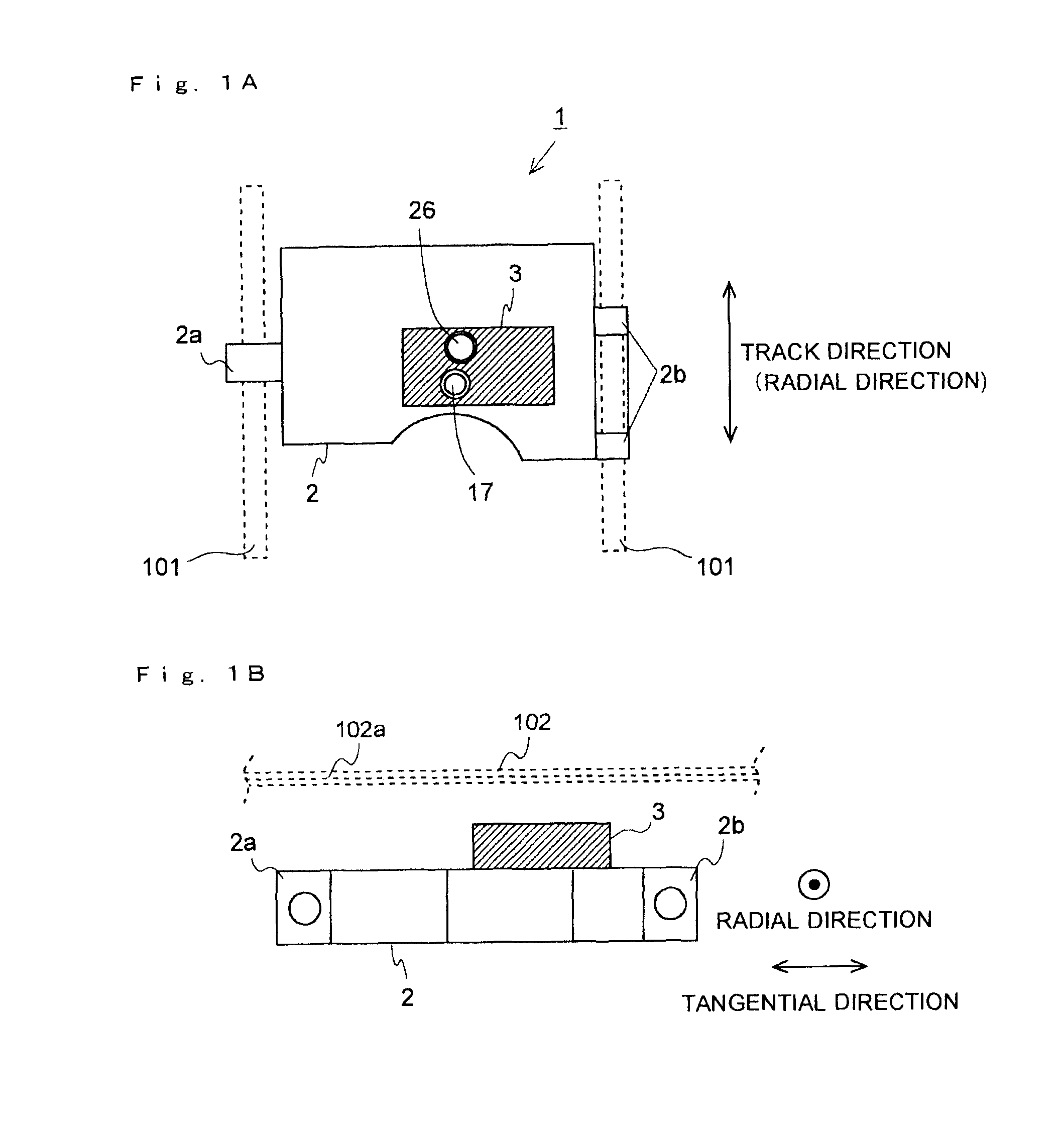
[0036]FIG. 1A is a schematic plan view showing the configuration of an optical pickup of this embodiment. FIG. 1B is a schematic side view showing the configuration of the optical pickup of this embodiment. As shown in FIGS. 1A and 1B, the optical pickup 1 of this embodiment is provided with a pickup base 2 and an objective lens actuator 3 mounted on the pickup base 2.

[0037]When information stored on an optical disc 102 is read, the optical pickup 1 is used by being moved in the radial direction of the optical disc 102. Thus, on the right and left of the pickup base 2 in the optical pickup 1, there are provided bearing portions 2a and 2b; the optical pickup 1 is held such that it can slide on two guide shafts 101 extending in the radial direction.

[0038]The optical pickup 1 is moved by an unillustrated known movement mechanism. As an example ...


PUM

PropertyMeasurementUnit
wavelength bandaaaaaaaaaa
angleaaaaaaaaaa
wavelength bandaaaaaaaaaa

Abstract

An optical pickup has a first optical system and a second optical system. The optical axis of the first optical system and the optical axis of the second optical system are inclined, for example, 45 degrees with respect to the reference plane, and are parallel to each other. A first objective lens and a second objective lens are arranged substantially side-by-side in a radial direction, and the center position of the second objective lens is slightly displaced from the reference plane in a tangential direction. The first optical system and the second optical system each have a flat-shaped beam splitter; this is used to produce astigmatism for acquiring a focus error signal by the astigmatic method.

Description

[0001]This application is based on Japanese Patent Application No. 2009-4770 filed on Jan. 13, 2009, the contents of which are hereby incorporated by reference.BACKGROUND OF THE INVENTION[0002]1. Field of the Invention[0003]The present invention relates to an optical pickup, and more particularly to the configuration of an optical pickup having two separate optical systems that are selectively used according to the type of optical disc.[0004]2. Description of Related Art[0005]Conventionally, optical pickups are used to read information on an optical disc and write information on the optical disc. There are a plurality of types of optical discs such as a compact disc (CD), a digital versatile disc (DVD) and a blue-ray disc (BD). Thus, for convenience and the like, among conventional optical pickups, there are some optical pickups that can be compatible with a plurality of types of optical discs.[0006]Among the optical pickups compatible with a plurality of types of optical discs, the...

Claims


Application Information

Patent Timeline
Patent Type & Authority Patents(United States)
IPC IPC(8): G11B7/00
CPCG11B7/0933G11B7/0935G11B7/1374
Inventor ITO, TATSUYA
Owner FUNAI ELECTRIC CO LTD
Why Eureka
Try Eureka