Guide for medical devices

a technology for medical devices and guides, applied in medical science, surgery, diagnostics, etc., can solve the problems of persistent control of the direction in which a medical device is deployed from a location, no device that accurately and easily guides medical devices in a plurality of separate branches, and achieves the effect of facilitating the automation of the deployment of medical devices

Inactive Publication Date: 2010-08-10
STEREOTAXIS
View PDF17 Cites 125 Cited by
  • Summary
  • Abstract
  • Description
  • Claims
  • Application Information

AI Technical Summary

Benefits of technology

[0005]Generally, the present invention relates to a guide for deploying a medical device in the body. The guide comprises a cannula, having a proximal end, a distal end, and lumen therebetween. There is a guide member, with a passage therethrough movably mounted in the lumen of the cannula. The guide member can be magnetically or mechanically moved to change the orientation of the passage in the guide member, and thus the direction of deployment of a medical device from the guide. The guide thus allows the direction of deployment of a medical device to be precisely controlled, and further allows a medical device to be deployed in a number of separate paths from the same device. The guide also facilitates the automation of the deployment of medical devices.

Problems solved by technology

Control of medical devices inside the body is a persistent problem.
A particular difficulty has been selectively controlling the direction in which a medical device is deployed from a location inside the body, for example while implanting a deep brain stimulator.
However there is no device that accurately and easily guides medical devices in a plurality of separate branches.
Similar problems are encountered when navigating through other body tissues.
Another difficulty with the prior art devices is the accurate navigation of medical devices in body lumens and cavities.

Method used


Image

  • Guide for medical devices
  • Guide for medical devices
  • Guide for medical devices

Examples


first embodiment

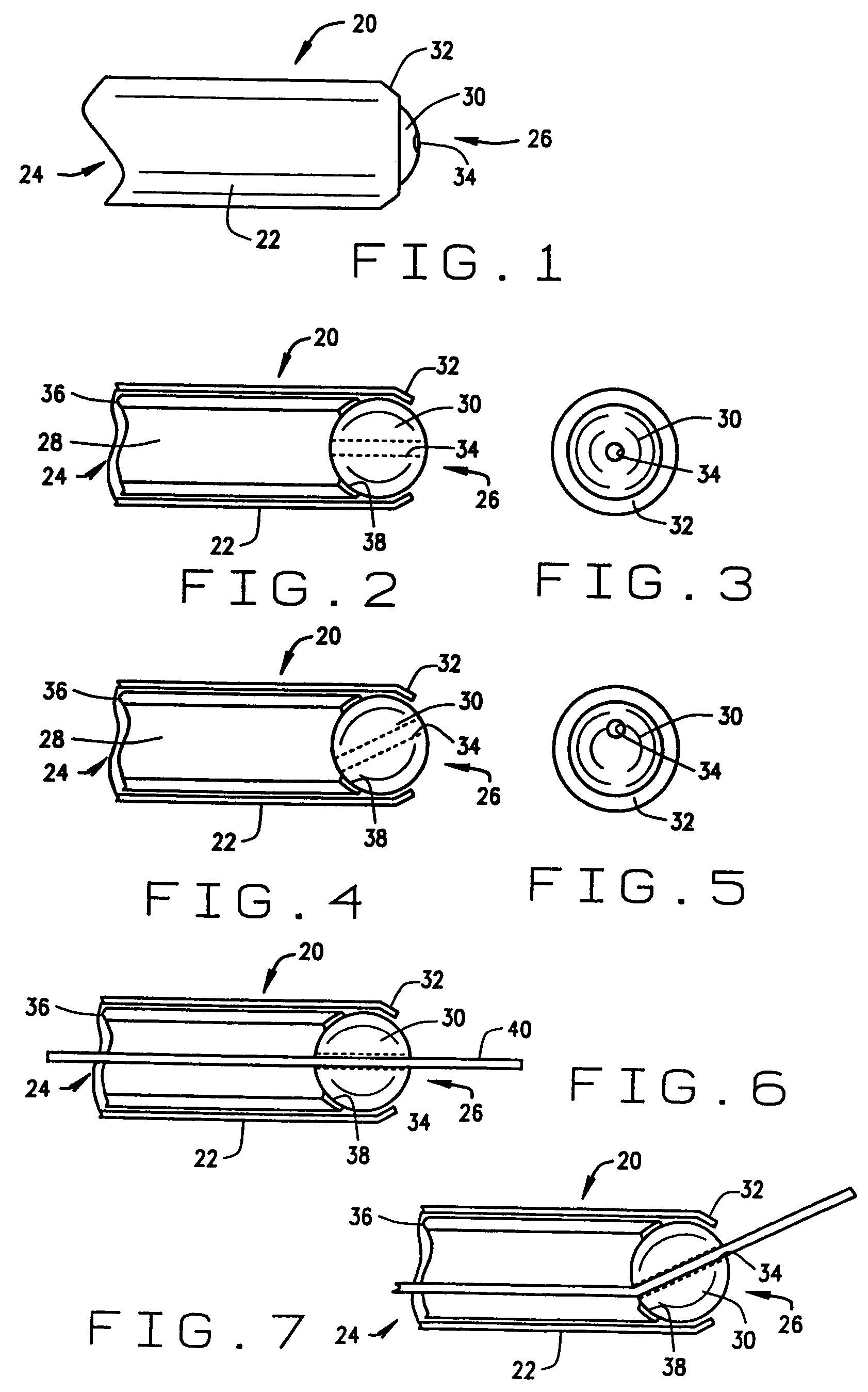
[0048]a guide for a medical device constructed according to the principles of this invention is indicated generally as 20 in FIGS. 1 through 5. The guide 20 comprises a cannula 22, having a proximal end 24, and a distal end 26, and a lumen 28 therethrough. The cannula 22 is preferably fairly stiff or rigid, made from any suitable material, such as a non-magnetic stainless steel. Of course in appropriate applications, the cannula 22 could be flexible. There is a guide member 30 in the cannula 22, mounted for movement in response to an applied magnetic field. In the first preferred embodiment shown in the Figures, the distal end 26 has a lip 32 for retaining the guide member 30 in the cannula. Me guide member 30 has a passage 34 therethrough for orienting or guiding a magnetic medical device.

[0049]The guide member 30 is preferably generally spherical, and the passage extends generally diametrically through the sphere. The guide member 30 is preferably made of a magnetic material so th...

second embodiment

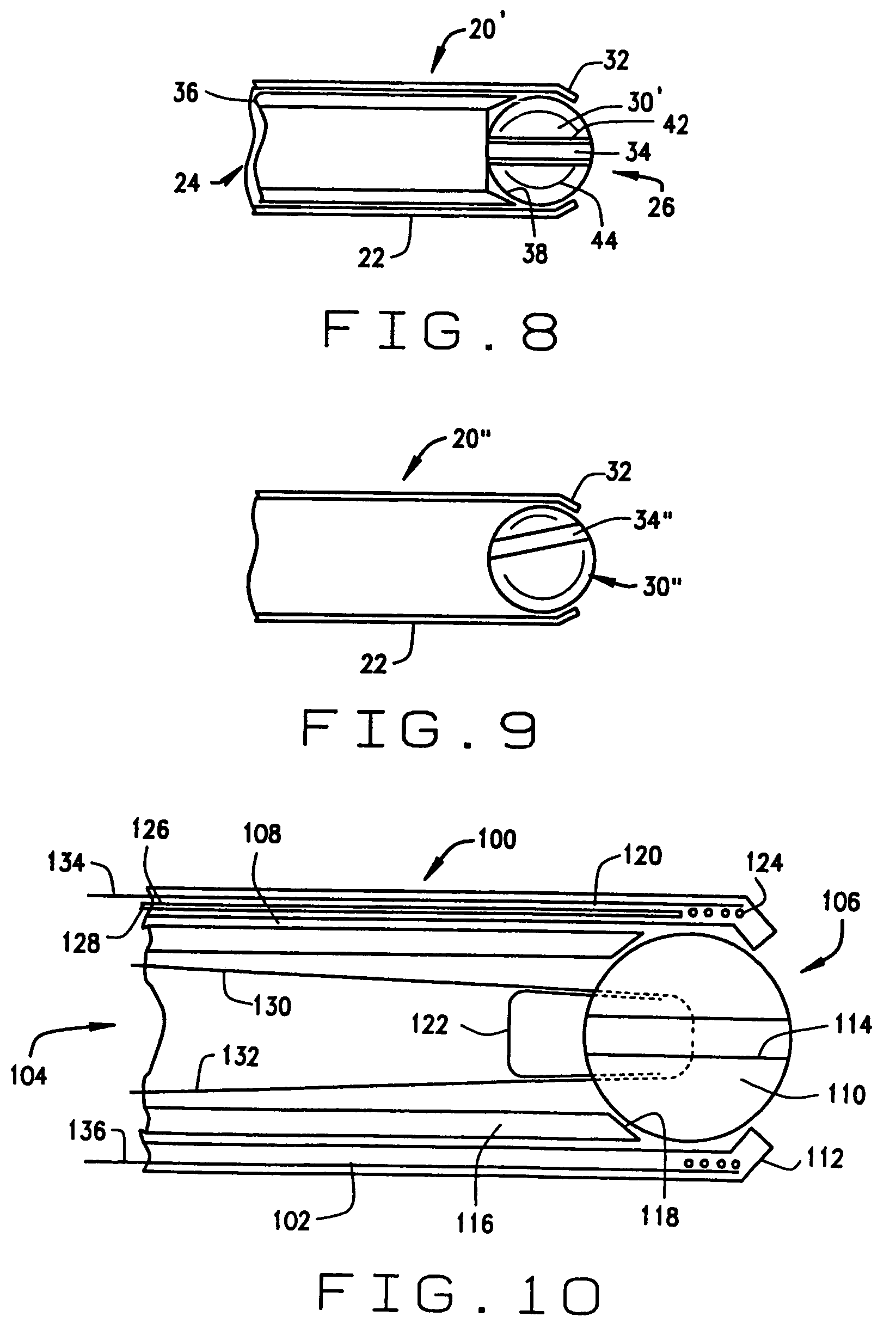
[0057]a guide constructed according to the principles of this invention is indicated generally as 100 in FIG. 10. The guide 100 comprises a cannula 102, having a proximal end 104, and a distal end 106, and a lumen 108 therethrough. The cannula 102 is preferably fairly stiff or rigid, made from any suitable material, such as a non-magnetic stainless steel. There is a guide member 110 in the cannula 102, mounted for movement in response to an applied magnetic field. In the first preferred embodiment shown in FIG. 10, the distal end 106 has a lip 112 for retaining the guide member 110 in the cannula. The guide member 110 has a passage 114 therethrough for orienting or guiding a magnetic medical device.

[0058]The guide member 110 is preferably generally spherical, and the passage 114 extends generally diametrically through the sphere. The guide member 110 is preferably made of a magnetic material so that the guide member moves in response to an externally applied magnetic field. This mag...

third embodiment

[0062]a guide for a medical device constructed according to the principles of this invention is indicated generally as 200 in FIGS. 11 through 14. The guide 200 comprises a cannula 202, having a proximal end 204, and a distal end 206, and a lumen 208 therethrough. The cannula 202 is preferably fairly stiff or rigid, made from any suitable material such as a non-magnetic stainless steel. There is a guide member 210 in the cannula 202, mounted for movement in response to an applied magnetic field. In the first preferred embodiment shown in the Figures, the distal end 206 has a lip 212 for retaining the guide member 210 in the cannula. The guide member 210 has a passage 214 therethrough for orienting or guiding a magnetic medical device.

[0063]The guide member 210 is preferably generally spherical, and the passage extends generally diametrically through the sphere.

[0064]The guide 200 preferably further comprises a lock for selectively locking the guide member 30 in a selected orientatio...


PUM


Abstract

A guide for controlling the orientation of a medical device includes a cannula having a lumen therein for the medical device, and a guide member having a passage therein for receiving and directing the medical device, the guide member being movably mounted in the cannula for movement. The guide member can be magnetically responsive to an externally applied magnetic field, or can be magnetically responsive to an externally applied magnetic field when a magnetic medical device is in the passage, and / or it can be mechanically responsive.

Description

CROSS REFERENCE TO RELATED APPLICATION[0001]This invention is a continuation of U.S. patent application Ser. No. 10 / 378,547, filed Mar. 3, 2003, now abandoned, which is a continuation of U.S. patent application Ser. No. 09 / 875,279, filed Jun. 6, 2001, now U.S. Pat. No. 6,527,782, which claims priority from U.S. Provisional Application Ser. No. 60 / 210,183, filed Jun. 7, 2000.BACKGROUND OF THE INVENTION[0002]This invention relates to medical devices, and in particular to a guide for controlling the orientation or direction of a medical device.[0003]Control of medical devices inside the body is a persistent problem. It is important to accurately control medical devices so that they quickly and effectively perform their diagnostic or therapeutic function, while minimizing collateral damage to surrounding tissue. A particular difficulty has been selectively controlling the direction in which a medical device is deployed from a location inside the body, for example while implanting a deep...

Claims


Application Information

Patent Timeline
Patent Type & Authority Patents(United States)
IPC IPC(8): A61B19/00A61B17/00A61B17/28A61B17/34A61M25/01A61M25/09A61M25/098
CPCA61B17/3417A61B17/3421A61B19/201A61M25/0127A61B2017/003A61B2017/2927A61B90/11
Inventor HOGG, BEVIL J.GARIBALDI, JEFFREY M.KLIMEK, SCOTT G.
Owner STEREOTAXIS
Why Eureka
Try Eureka