Filter system for catch basins

a filter system and catch basin technology, applied in the field of catch basins, can solve the problems of often including the water of the draining water

Active Publication Date: 2010-08-10
LUCAS CHASSIDY
View PDF10 Cites 47 Cited by
  • Summary
  • Abstract
  • Description
  • Claims
  • Application Information

AI Technical Summary

Problems solved by technology

A problem is that the drainage water often includes debris and contaminants, and sometimes oil and grease.

Method used


Image

  • Filter system for catch basins
  • Filter system for catch basins
  • Filter system for catch basins

Examples


Embodiment Construction

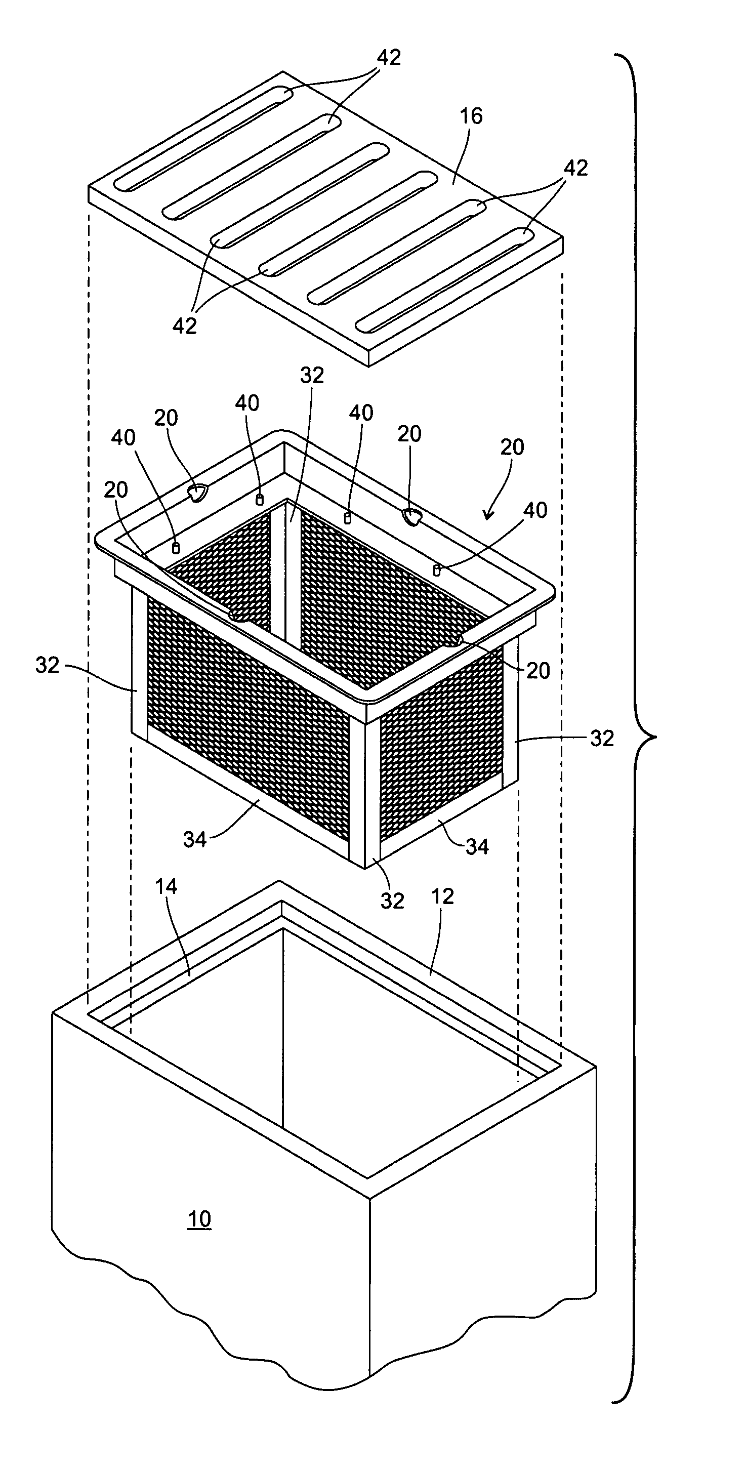
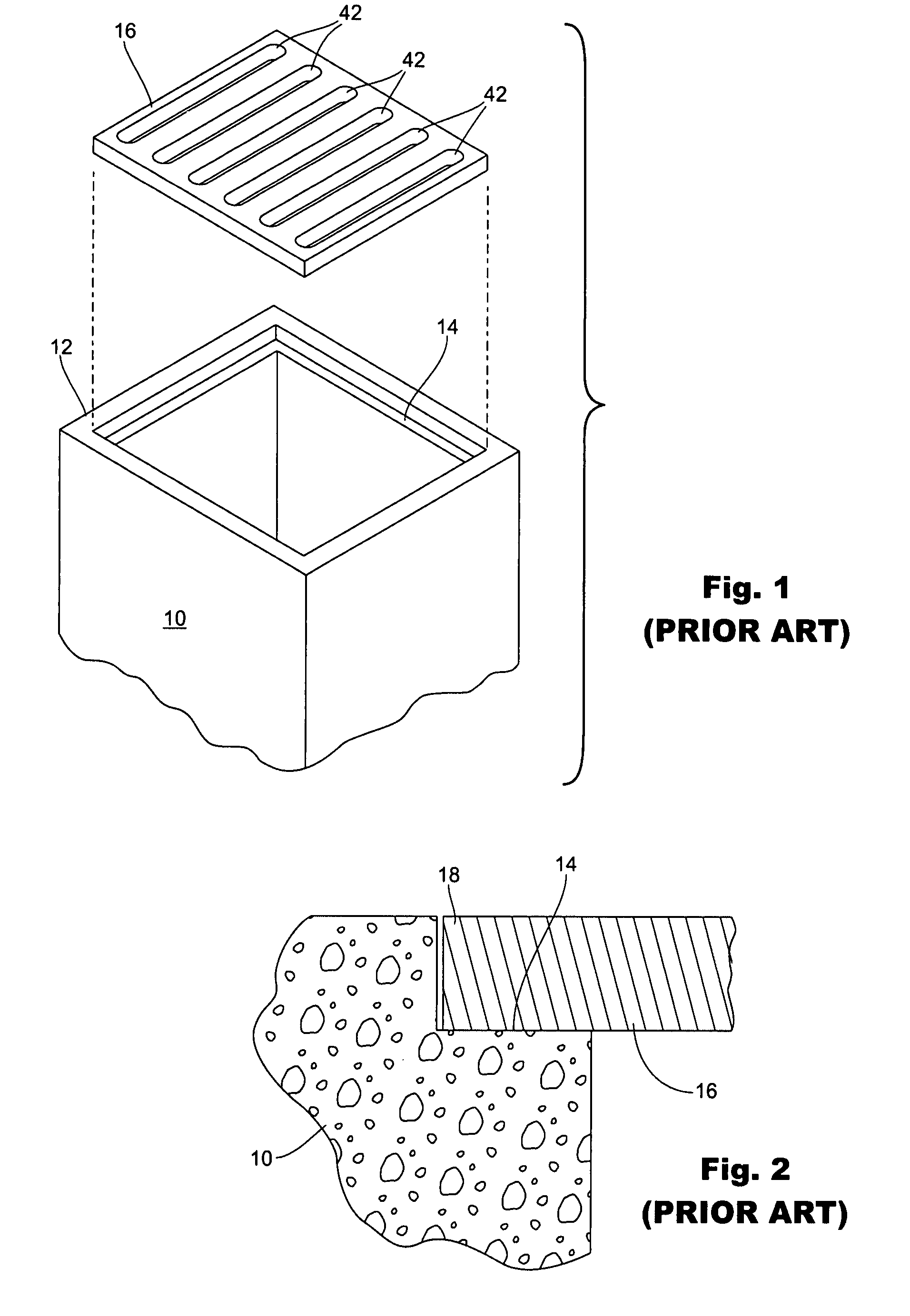
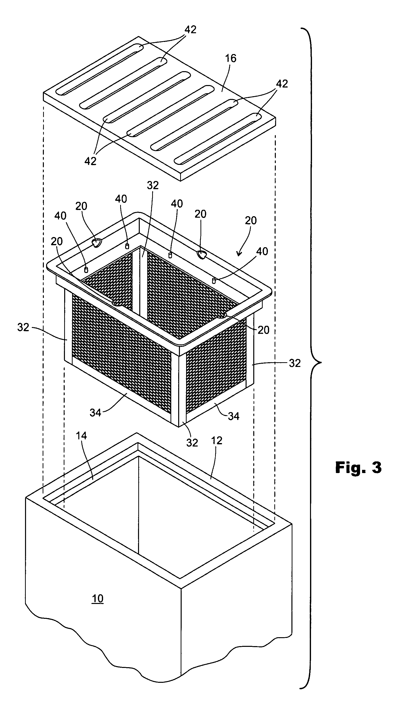
[0025]FIGS. 1 and 2 show a conventional catch basin 10 which is typically constructed from concrete and includes closed side and bottom walls and an open top. The top is surrounded by a rim 12 and a shoulder 14 spaced below the rim 12. Shoulder 14 normally receives and supports a grate 16 which is typically constructed from cast iron. FIG. 2 shows an edge portion 18 of the grate 16 resting on the shoulder 14. FIG. 3 shows a filter basket 20 that is adapted to fit down inside the catch basin 10. Filter basket 20 has an upper rim portion 22 comprising an upper flange 24, a lower flange 26 and a vertical wall 28. Actually, upper rim structure 22 has four flanges 24, four flanges 26, and four walls 28. Each flange 24 projects laterally outwardly from its wall 28 and each flange 26 projects laterally inwardly from its wall 28. Flanges 24 and 26 are parallel to each other and perpendicular to the walls 28, as clearly shown by FIG. 4.

[0026]In addition to the upper rim structure 22, the bas...


PUM

PropertyMeasurementUnit
structuresaaaaaaaaaa
cylindrical shapeaaaaaaaaaa
lengthsaaaaaaaaaa

Abstract

A first filter basket (20) sits down into a catch basin (10) and has an upper flange (24) that rests on a shoulder (14) provided in the catch basin (10) for supporting a grate (16). The filter basket (20) has expanded metal side and bottom walls which are adapted to pass liquid and catch particulate material larger in size than the wall openings. A geo-textile liner (42) is optionally positioned inside of the filter basket (20). The liner (42) is supported on a lower rim flange (26). Posts (40) on the rim flange (26) extend upwardly through openings (66) in marginal portions of the liner (42). A smaller second filter basket (72) is optionally supported inside the larger first filter basket (20). An absorbent pillow (90) may be positioned between the bottoms of the two filter baskets (20, 72) to catch and absorb oils and greases that are in the liquid that enters the catch basin (10).

Description

TECHNICAL FIELD[0001]The present invention relates to catch basins used in drainage systems. More particularly, it relates to a filter system for removing debris and contaminants, including oil and grease from the drain water so that they will not enter the system of drainage pipes to which the catch basins are connected.BACKGROUND OF THE INVENTION[0002]It is common to collect drainage water by use of a system of catch basins which are buried in the ground and are connected to a network of drain pipe. A problem is that the drainage water often includes debris and contaminants, and sometimes oil and grease. It is not desirable for these contaminants to get into the drain water which is expect to eventually reenter the earth's rivers, etc. which include fish, etc. There is a need for an effective and economic system for removing the debris and contaminants from the drainage water. The main object of this invention is to fill this need by providing a filter system installable into the ...

Claims


Application Information

Patent Timeline
Patent Type & Authority Patents(United States)
IPC IPC(8): E03F5/06
CPCE03F1/00E03F5/0401E03F5/0404
Inventor LUCAS, CHASSIDY
Owner LUCAS CHASSIDY
Why Eureka
Try Eureka