
Web for separating conductors in a communication cable

a technology for separating conductors and communications cables, applied in the direction of insulated conductors, cables, conductors, etc., can solve the problems of mode signal noise, reduced cross talk between adjacent cables, and given cable distances the same distan

Active Publication Date: 2010-08-10
BELDEN INC
View PDF28 Cites 21 Cited by
  • Summary
  • Abstract
  • Description
  • Claims
  • Application Information

AI Technical Summary

Benefits of technology

The present invention provides telecommunications cables with improved performance. The cables have a cable jacket with a spline and insulation made from a material with a matching dielectric constant. The cable also has ridges or distensions on its inner surface to prevent contact between the conductor assembly and the inner surface. The separator spline has H-shaped dividing strips that twist helicoidally along its length. These improvements enhance the cable's ability to transmit signals with low loss and reduce interference.

Problems solved by technology

One problem which must be surmounted when implementing high speed data communications such as the 10 Gigabit Ethernet is the reduction in cross talk between adjacent cables, typically referred to as Power Sum Alien Near End Cross (PSANEXT) and Power Sum Alien Equal Level Far End Cross Talk (PSAELFEXT).
One drawback of these prior art designs is that when such prior art cables are placed adjacent to one another (as is typically the case in cable runs and conduit and the like), the twisted pairs having the longest twist in a given cable are the same distance from the geometric centre of the cable as the other twisted pairs.
In addition, each individual pair exhibits relatively high levels of unbalance known to cause common mode signal noise.
This can lead to a degradation in the performance of (and therefore the signals being transmitted by) each of the cables which cannot be compensated for due to the large number of noise signals originating from like pairs of a typically a large number of adjacent cables (up to 6 adjacent cables and 48 disturbing twisted pairs of conductors in a worst case).

Method used


Image

  • Web for separating conductors in a communication cable
  • Web for separating conductors in a communication cable
  • Web for separating conductors in a communication cable

Examples


Embodiment Construction

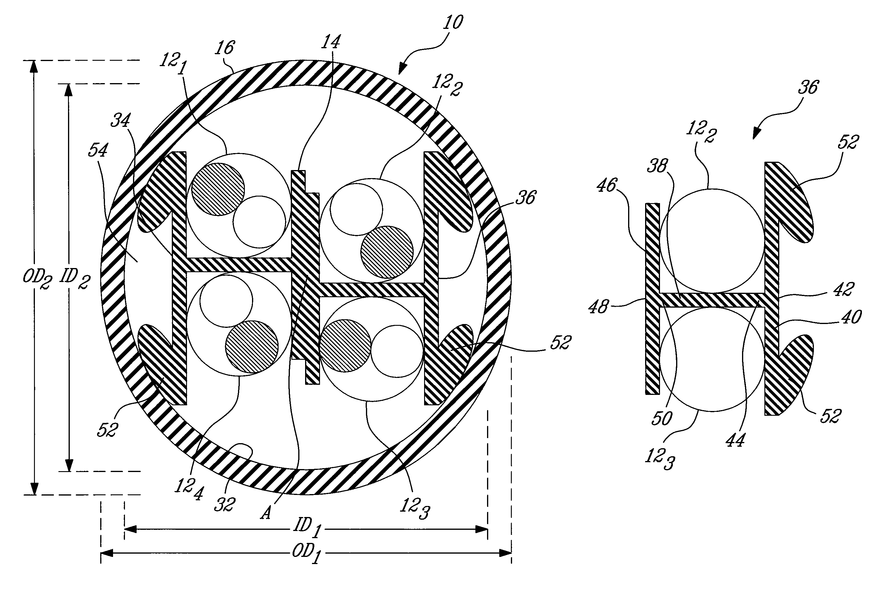
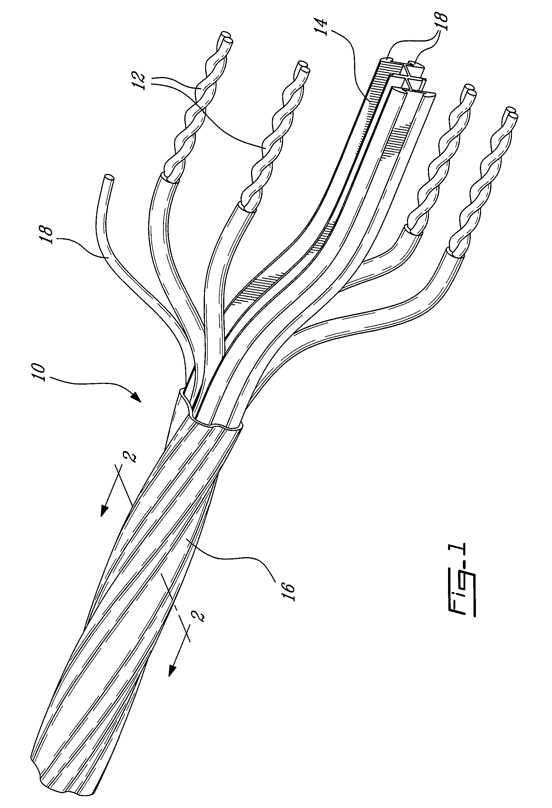
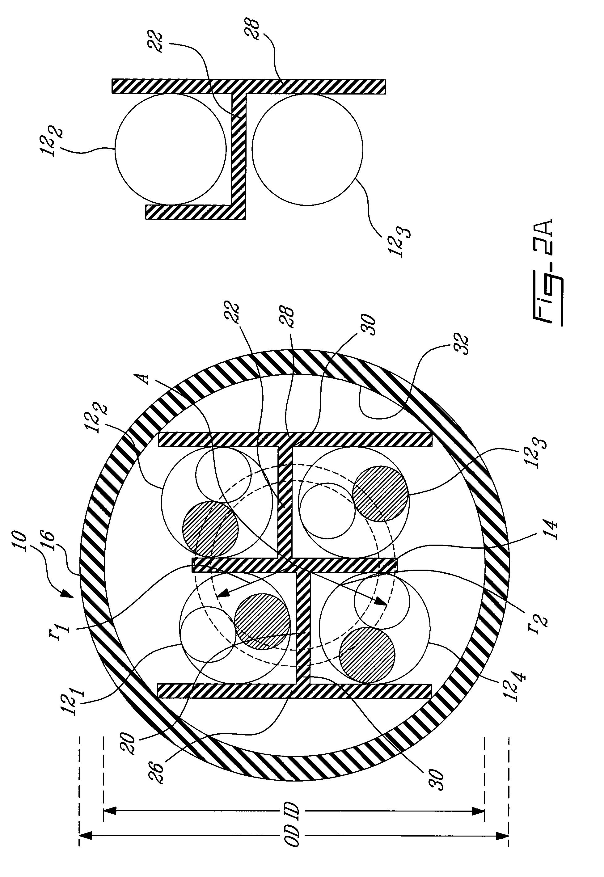
[0015]Referring now to FIG. 1, a telecommunications cable, generally referred to using the reference numeral 10, will now be described. The cable 10, is comprised of four (4) twisted pairs of conductors 12 separated by a separator web 14 and encased in a cable jacket 16. In a particular embodiment one or more filler elements as in 18 can be included positioned between the cable jacket 16 and the conductors 12. Additionally, a shielding foil or the like (not shown) may also be included between positioned between cable jacket 16 and the filler elements 18.

[0016]Still referring to FIG. 1, as known in the art, the twisted pairs of conductors 12 are typically twisted with different twist lays (i.e. number of twists per unit length). These twist lays can be regular and predetermined or can vary along the length of the cable 10, for example between a maximum and a minimum value. In the latter case, the twist lays can vary either randomly or in accordance with a predetermined pattern (for e...


PUM

PropertyMeasurementUnit
dielectric constantaaaaaaaaaa
conductiveaaaaaaaaaa

Abstract

A telecommunications cable having a cable jacket defining an elongate cable core, a conductor assembly comprising four twisted pairs of conductors disposed along the core and parallel elongate distensions formed on an inner surface of the cable jacket. The distensions are spaced about an inner surface of the cable jacket and prevent the conductor assembly from coming into contact with the inner surface. The distensions can be the result of a series of filler elements placed between the cable jacket and the cable core and which wind helicoidally along and about the cable core. A separator spline has first and second elongate dividing strips having a substantially H shaped cross section and arranged side by side. The spline twists helicoidally along its length. The separator spline and the insulation surrounding the twisted pairs of conductors can be manufactured form a material having the same dielectric constant.

Description

CROSS REFERENCE TO RELATED APPLICATIONS[0001]The present application claims priority from U.S. Provisional Application No. 60 / 778,930 filed on Mar. 6, 2006, Canadian Patent Application No. 2,538,637 filed on Mar. 6, 2006, and U.S. Provisional Application No. 60 / 885,691 filed on Jan. 19, 2007, the entirety of which is incorporated herein by referenceFIELD OF THE INVENTION[0002]The present invention relates to a web for separating conductors in a communications cable. In particular, the present invention relates to a cross talk reducing separator web, or spline, which ensures predetermined positioning of twisted pairs of conductors relative to one another.BACKGROUND TO THE INVENTION[0003]One problem which must be surmounted when implementing high speed data communications such as the 10 Gigabit Ethernet is the reduction in cross talk between adjacent cables, typically referred to as Power Sum Alien Near End Cross (PSANEXT) and Power Sum Alien Equal Level Far End Cross Talk (PSAELFEXT)...

Claims


Application Information

Patent Timeline
Patent Type & Authority Patents(United States)
IPC IPC(8): H01B7/00
CPCH01B11/06H01B11/04H01B7/189H01B11/005
Inventor VEXLER, GAVRIELGAREIS, GALEN
Owner BELDEN INC
Learn More