Additive manufacturing forming cylinder drive mechanism, forming cylinder and additive manufacturing equipment

A driving mechanism and additive manufacturing technology, which is applied in the direction of additive manufacturing, additive processing, process efficiency improvement, etc., can solve the problem of limited forming height of forming equipment, achieve force optimization, improve stability, and increase forming height Effect

Active Publication Date: 2017-01-11
XIAN BRIGHT ADDTIVE TECH CO LTD
View PDF20 Cites 7 Cited by
  • Summary
  • Abstract
  • Description
  • Claims
  • Application Information

AI Technical Summary

Problems solved by technology

[0004] The purpose of the present invention is to provide a driving mechanism for forming cylinders for additive manufacturing, which solves the technical problem that the existing driving mechanism causes the forming height of the forming equipment to be limited

Method used


Image

  • Additive manufacturing forming cylinder drive mechanism, forming cylinder and additive manufacturing equipment

Examples


Embodiment 1

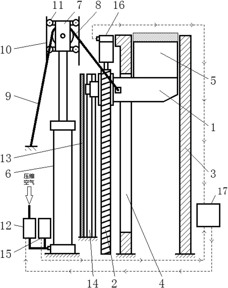
[0023] The additive manufacturing forming cylinder driving system of the present invention includes a cantilever lifting system and a dynamic compensation system.

[0024] In a structure of the drive system, the cantilever lifting system includes a cantilever 1 and a screw drive mechanism 2, such as figure 1 As shown, one end of the cantilever 1 is installed on the screw drive mechanism 2 , and the other free end is used to fix the base plate 5 . The screw driving mechanism 2 drives the cantilever 1 to feed up and down, and drives the base plate 5 to lift. One side of the screw drive mechanism 2 is provided with a slider slide rail mechanism 14, which is connected with the cantilever 1, and assists the cantilever 1 to move up and down to ensure that the cantilever 1 moves up and down in the vertical direction. A force sensor is arranged on the upper surface of the cantilever 1 for measuring and feeding back the downward load force on the cantilever.

[0025] The dynamic comp...

Embodiment 2

[0029] In another structure of the drive system, the structure of the cantilever lifting system is the same as in Embodiment 1, the difference is that no force sensor is set on the cantilever 1, and the cantilever lowering height or Servo motor torque, and height data or torque data are fed back to the controller 17 of the driving system, and the downward load force that cantilever is subjected to under this height or torque is obtained by calculation, and then the inlet air pressure of the air pressure regulator 12 is adjusted to make it The upward compensating force is balanced by the downward load on the cantilever. The structure of the dynamic compensation system is the same as in Embodiment 1, the difference is that the movable pulley system is composed of a sprocket, a chain and a sprocket support structure.

Embodiment 3

[0031] In another structure of the drive system, the structure of the cantilever lifting system is the same as in Embodiment 1, the difference is that no force sensor is set on the cantilever 1, and a height measuring device is set on the screw drive mechanism 2 to measure and feed back the cantilever drop. As far as the controller 17 of the drive system is concerned, a grating scale 13 is provided on one side of the screw drive mechanism. The structure of the dynamic compensation system is the same as in Embodiment 1.

[0032] The working process of the above-mentioned additive manufacturing forming cylinder driving mechanism is as follows: on the one hand, the screw driving mechanism 2 drives the cantilever 1 to feed up and down, and drives the substrate 5 to move up and down. The cantilever lifting system is used to replace the piston drive mechanism, so that the height of the additive manufacturing equipment can be greatly increased under the condition of limited height. ...


PUM


Abstract

The invention discloses an additive manufacturing forming cylinder drive mechanism which comprises a cantilever lifting system and a dynamic compensation system. The cantilever lifting system comprises a cantilever and a cantilever drive mechanism. The cantilever comprises an installation end installed on the cantilever drive mechanism and a free end used for fixing a base plate. The cantilever drive mechanism drives the cantilever to conduct vertical feeding. The dynamic compensation system is connected with the cantilever and provides upward compensation force for the cantilever. The invention further discloses a forming cylinder with the drive mechanism and additive manufacturing equipment. According to the forming cylinder drive mechanism, the cantilever drive mechanism is used for replacing a piston drive mechanism so that the forming height of the additive manufacturing equipment can be greatly increased under the condition of the limited height; and meanwhile, the upward compensation force is provided for the cantilever in the descending process through the arranged dynamic compensation system, stress of the cantilever in the descending process is optimized, and the stability of the forming cylinder drive mechanism is improved.

Description

technical field [0001] The invention belongs to the technical field of additive manufacturing equipment, and in particular relates to a driving mechanism of a forming cylinder for additive manufacturing, and also relates to a forming cylinder with the driving mechanism and additive manufacturing equipment. Background technique [0002] Additive manufacturing technology is based on three-dimensional CAD model data, by adding materials and manufacturing them layer by layer. It is based on the computer three-dimensional design model, through the software layered discrete and numerical control forming system, the material is piled up layer by layer with high-energy beams, and finally superimposed and formed to produce a physical product. [0003] In order to ensure good sealing of metal powder, the forming cylinder of the existing additive manufacturing equipment generally adopts a piston-type lifting mechanism, that is, the forming platform is driven up and down by the screw fr...

Claims


Application Information

Patent Timeline
Patent Type & Authority Applications(China)
IPC IPC(8): B22F3/105B33Y30/00
CPCB22F3/003B33Y30/00B22F10/10B22F10/00B22F12/90B22F12/222B22F10/20Y02P10/25
Inventor 程锦泽薛蕾詹云王石开杨东辉
Owner XIAN BRIGHT ADDTIVE TECH CO LTD
Why Eureka
Try Eureka