Image forming apparatus and control method thereof

a technology of image forming apparatus and control method, which is applied in the direction of electrographic process apparatus, printing, instruments, etc., can solve the problems of frictional force always exist between the photosensitive drum and the intermediate transfer belt, tend to generate a transfer failure, and difficult optimal setting of primary transfer current, etc., to suppress non-uniformity and avoid influence

Inactive Publication Date: 2010-08-10
CANON KK
View PDF14 Cites 5 Cited by
  • Summary
  • Abstract
  • Description
  • Claims
  • Application Information

AI Technical Summary

Benefits of technology

[0026]It is an object of the present invention to provide an image forming apparatus capable of avoiding the influence of a dispersed dots image on a patch image as well as suppressing nonuniformity such as a undesirable line-like image when forming a patch image for color stabilization control, and a control method of the image forming apparatus.
[0039]The present invention can avoid the influence of a dispersed dots image on a patch image, that is, stabilize transfer as well as suppressing nonuniformity such as a undesirable line-like image when forming a patch image for color stabilization control.

Problems solved by technology

However, a small primary transfer current tends to generate a transfer failure, while a large primary transfer current tends to cause retransfer.
It is difficult to optimally set the primary transfer current.
However, a frictional force always exists between the photosensitive drum and the intermediate transfer belt owing to the peripheral speed difference.
As a result, when forming an electrostatic latent image on the photosensitive drum, exposure fluctuates, therefore, generating a undesirable line-like image.
For example, even in an image forming apparatus in which no peripheral speed difference is set between the image carrier and the transfer moving means, an unintended peripheral speed difference is generated owing to decentering of the driving roller or the like, thereby causing color misregistration, as described in Japanese Patent Laid-Open No. 11-52758.
Hence, by this toner patch based control, the influence of the fixing process and subsequent processes cannot be reflected on the detected toner density.
However, this technique is poor in operability because the user must carry a transfer medium on which an output image is formed to the reader.
In many cases, the user does not periodically print a patch image and control toner density because it is troublesome.
Thus, color stabilization is one of most important issues even in a direct imaging type image forming apparatus.
If no dispersed dots image is formed when forming a patch image in order to avoid this influence, a undesirable line-like image is formed on the patch image due to a change of the coefficient of friction, and the sensed density value fluctuates as shown in FIG. 22, thereby failing accurate measuring.

Method used


Image

  • Image forming apparatus and control method thereof
  • Image forming apparatus and control method thereof
  • Image forming apparatus and control method thereof

Examples


first embodiment

Example of Image Forming Apparatus

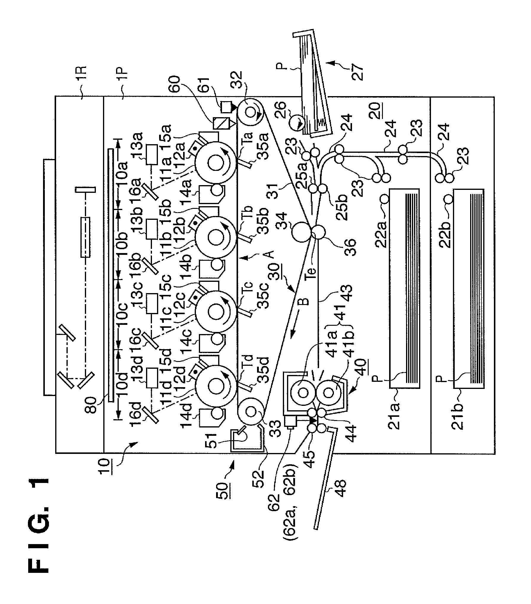
[0069]FIG. 1 is a sectional view of the main part of an image forming apparatus according to the embodiments of the present invention.

[0070]In the embodiments, the image forming apparatus is of an electrophotographic type, and comprises a reader portion 1R and printer portion 1P.

[0071]The reader portion 1R optically reads a document image, converts it into an electrical signal, and transmits the electrical signal to the printer portion 1P.

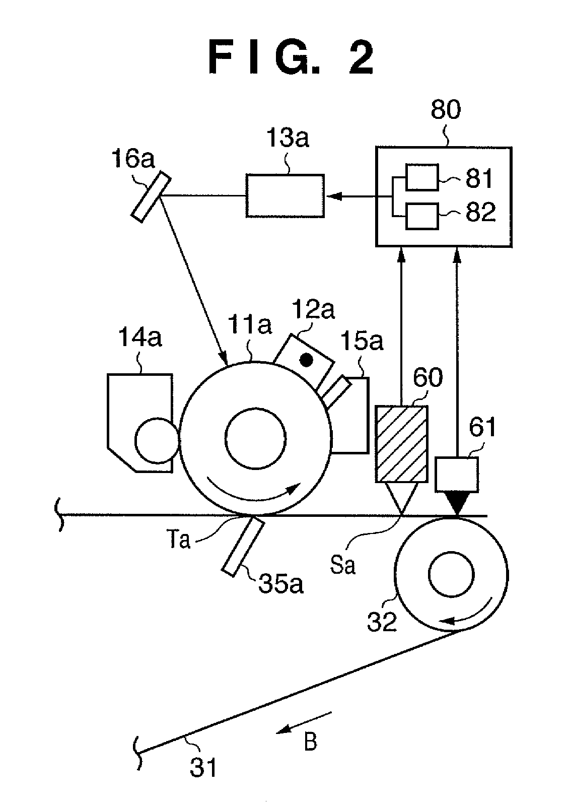
[0072]The printer portion 1P comprises four tandem image forming units 10, that is, 10a, 10b, 10c and 10d, a sheet feeding unit 20, an intermediate transfer unit 30, a fixing unit 40, a cleaning unit 50, a registration sensor 60, and a control unit 80.

[0073]The four tandem image forming units 10a to 10d have the same arrangement. In the image forming units 10a to 10d, drum type electrophotographic photosensitive members or photosensitive drums 11, that is, 11a to 11d serving as the first image carriers are axially ...

second embodiment

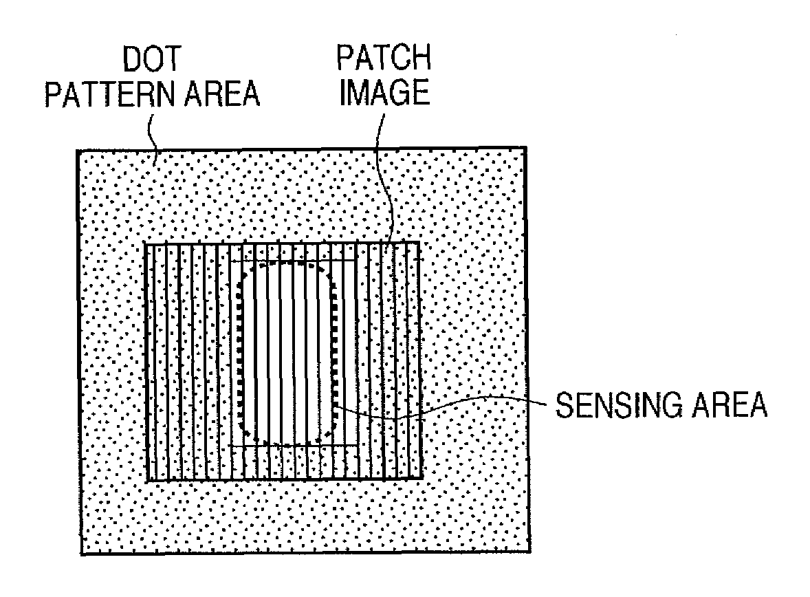
[0140]The second embodiment is different from the first embodiment in that a dot toner image is formed like a band in the sub-scanning direction.

[0141]Similar to the first embodiment, the second embodiment will exemplify a case where a patch image for a color sensor is formed.

Example of Forming Image According to Second Embodiment

[0142]A method of generating image data to be input to an exposure unit 13d of the image forming unit 10d when forming a patch image will be described with reference to FIG. 14.

Example of Generating Image Data According to Second Embodiment

[0143]FIG. 14 is a block diagram of the schematic arrangements of the control unit 80 and the exposure unit 13d of the image forming unit 10d. The arrangement in FIG. 14 is different from that in FIG. 5 in that an area signal generation unit 108-2 does not output a sub-scanning dot pattern area signal (f) to a logical operation circuit 110-2.

[0144]In FIG. 14, image information input from a host PC 101 or reader portion 1R...

third embodiment

[0155]The third embodiment is different from the first embodiment in that a dot toner image is formed like a band in the main-scanning direction.

[0156]Similar to the first embodiment, the third embodiment will exemplify a case where a patch image for a color sensor is formed.

Example of Forming Image According to Third Embodiment

[0157]A method of generating image data to be input to an exposure unit 13d of the image forming unit 10d when forming a patch image will be described with reference to FIG. 17.

Example of Generating Image Data According to Third Embodiment

[0158]FIG. 17 is a block diagram of the schematic arrangements of the control unit 80 and the exposure unit 13d of the image forming unit 10d. The arrangement in FIG. 17 is different from that in FIG. 5 in that an area signal generation unit 108-3 does not output a main-scanning dot pattern area signal (e) to a logical operation circuit 110-3.

[0159]In FIG. 17, image information input from a host PC 101 or reader portion 1R i...


PUM


Abstract

An area signal generation unit and a logical operation circuit control a dot pattern forming unit which forms a dispersed dots image by dispersing dot developer images each having the area of at least one dot, so as not to form a dot pattern in the area of a patch image to be formed by a patch image forming unit or the sensing area of the patch image. An image forming apparatus capable of avoiding the influence of a dispersed dots image on a patch image with suppressing nonuniformity caused by a line-like image when forming a patch image for color stabilization control, is provided.

Description

BACKGROUND OF THE INVENTION[0001]1. Field of the Invention[0002]The present invention relates to an image forming apparatus using an electrostatic method or electrophotographic printing method, and a control method of the image forming apparatus.[0003]2. Description of the Related Art[0004]Related arts for the present invention will be described by classifying them into a transfer stabilization technique and a color stabilization technique.[0005]<Transfer Stabilization Technique>[0006]There has conventionally been known an image forming apparatus having a plurality of image forming units.[0007]Each image forming unit forms an electrostatic latent image on an image carrier such as a photosensitive drum by irradiating the image carrier with a modulated laser beam or light from a light emitting element such as an LED in accordance with image information. The electrostatic latent image is developed as a toner image by a developing means which stores a developer (toner). The toner ...

Claims


Application Information

Patent Timeline
Patent Type & Authority Patents(United States)
IPC IPC(8): G03G15/00B41J2/47
CPCG03G15/0131G03G15/5058G03G2215/00059G03G2215/0016G03G2215/0129G03G2215/0161
Inventor TAMAOKI, TOMOHIRO
Owner CANON KK
Why Eureka
Try Eureka