Shrink fitting method including deformation

a technology of shrink fitting and deformation, which is applied in the direction of non-disconnectible pipe joints, manufacturing tools, couplings, etc., can solve the problems of inability to widely use shrink fittings for general industrial parts, difficulty in practical use due to accuracy, and simple shrink fitting principles

Inactive Publication Date: 2010-08-17
KOREA INST OF SCI & TECH
View PDF11 Cites 12 Cited by
  • Summary
  • Abstract
  • Description
  • Claims
  • Application Information

AI Technical Summary

Benefits of technology

[0012]Therefore, an object of the present invention is to provide a new shrink fitting method that does not require an accurate process.

Problems solved by technology

The principle of shrink fitting is very simple but has difficulty in practical use due to accuracy.
Since the change of the diameter is in the range of 0.5% (0.45% if heated at 300° C. because thermal expansion coefficient of metal is generally 15×10−6 / ° C.) due to thermal expansion, shrink fitting is not suitable for the industrial pipe or rod material.
Thus, shrink fitting cannot be widely used for general industrial parts because it is available only when accurate mechanical process follows.

Method used


Image

  • Shrink fitting method including deformation
  • Shrink fitting method including deformation
  • Shrink fitting method including deformation

Examples


example 1

Pipe Bonding 1

[0046]If welding is used for bonding between pipes, it is likely that a defect occurs to cause breakdown, and process steps are complicated to cause expensive cost.

[0047]Also, since metals having high reactivity, such as titanium, require welding condition, technical difficulty exists. Accordingly, a mechanical bonding method that does not require welding can be widely used for bonding between pipes.

[0048]However, since most of mechanical coupling parts have complicated structures, are expensive, and have difficulty in sealing, it is difficult to use them at high pressure. Although a method of bonding pipes using a shape memory alloy is being developed, this method is not generally used because the cost of the alloy is expensive and sealing is not solved.

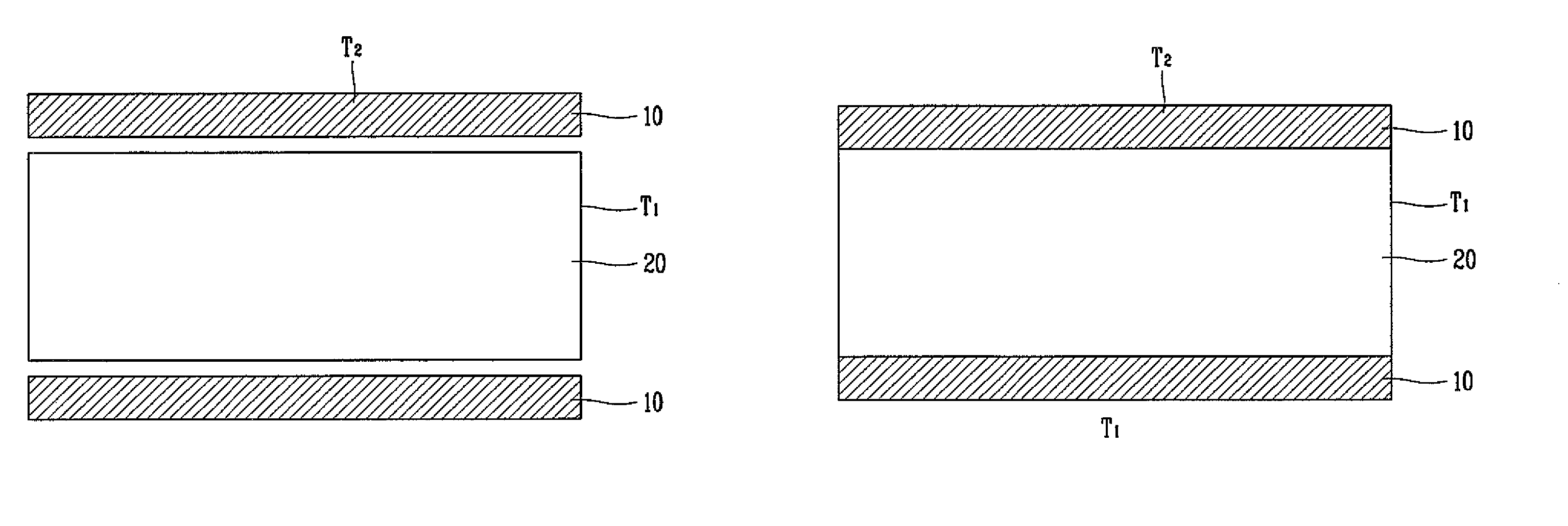
[0049]It is generally known that the industrial pipe has a diameter error in the range of 2% considering the genuine circle. Since the diameter of the industrial pipe is varied in the range of 0.5% due to thermal expan...

example 2

Pipe bonding 2

[0058]Pipe bonding can be used for the case where the coupling 50 is inserted into the pipe 30.

[0059]Referring to FIGS. 5A to 5E, the coupling 50 is prepared to have an outer diameter smaller than an inner diameter of the pipe 30 heated at T2 (FIG. 5A). Then, the end of the pipe 30 is heated (FIG. 5B) and the coupling 50 is inserted into the pipe 30 (FIG. 5C).

[0060]If the diameter of the pipe 30 is reduced so as not to generate a gap between the coupling 50 and the pipe 30 (FIG. 5D), the pipe 30 is cooled at T1 to generate a strong bonding force F with the coupling 50 (FIG. 5E).

[0061]It has been described that the coupling 50 is heated in the example 1 referring to FIGS. 4A to 4D while the end of the pipe 30 is heated in the example 2 referring to FIGS. 5A to 5E. To increase the difference in temperature between the pipe 30 and the coupling 50, it is more effective that the end of the pipe 30 should be cooled in the example 1 while the coupling 50 should be cooled in t...


PUM

PropertyMeasurementUnit
shrink fittingaaaaaaaaaa
outer diametersaaaaaaaaaa
inner diameteraaaaaaaaaa

Abstract

A new shrink fitting method including deformation is disclosed, in which a high bonding force can be obtained without accurate mechanical process such as forming an insertion body having an outer diameter greater than an inner diameter of an object for receiving the insertion body. The shrink fitting method comprises preparing a pipe and a rod material whose inner and outer diameters are different from each other; bonding the pipe and the rod material to each other in a state that the pipe or the rod material is deformed by heating; deforming the pipe to allow the inner diameter of the pipe to be equal to the outer diameter of the rod material; and cooling the bonded pipe and rod material. The shrink fitting method can be widely used for various mechanical parts.

Description

RELATED APPLICATION[0001]The present disclosure relates to subject matter contained in priority Korean Application No. 10-2005-0104589, filed on Nov. 02, 2005, which is herein expressly incorporated by reference in its entirety.BACKGROUND OF THE INVENTION[0002]1. Field of the Invention[0003]The present invention relates to a shrink fitting method, and more particularly, to a new shrink fitting method including deformation, in which a high bonding force can be obtained without accurate mechanical process such as forming an insertion body having an outer diameter greater than an inner diameter of an object for receiving the insertion body.[0004]2. Description of the Background Art[0005]Shrink fitting is metal bonding technique using expansion and shrinkage of metal due to heat, and is widely used for mechanical parts owing to advantages of mechanical bonding with no welding defect and simple process.[0006]The principle of shrink fitting will be described as follows. For example, suppo...

Claims


Application Information

Patent Timeline
Patent Type & Authority Patents(United States)
IPC IPC(8): B23P11/00F16B4/00B23P11/02
CPCB23P11/025F16B4/006F16B17/004Y10T29/49865Y10T29/49925Y10T403/4991Y10T29/49927Y10T29/49929Y10T403/4966Y10T29/49913Y10T403/48B23P19/00B23P19/02
Inventor JEE, KWANG-KOOHAN, JUN-HYUNKIM, YOON-BAE
Owner KOREA INST OF SCI & TECH
Why Eureka
Try Eureka