Fuel system with drain unit

a fuel system and drain unit technology, applied in the field of carburetors, can solve the problems of fuel spillage from a full float bowl, and achieve the effect of reducing or eliminating the possibility of fuel spillage from the carburetor during the movement or transport of the engine, and reducing the emission of hydrocarbons

a fuel system and drain unit technology, applied in the field of carburetors, can solve the problems of fuel spillage from a full float bowl, and achieve the effect of reducing or eliminating the possibility of fuel spillage from the carburetor during the movement or transport of the engine, and reducing the emission of hydrocarbons

US7775189B2Inactive Publication Date: 2010-08-17WALBRO ENGINE MANAGEMENT

Image

  • Fuel system with drain unit
  • Fuel system with drain unit
  • Fuel system with drain unit

Examples


Embodiment Construction

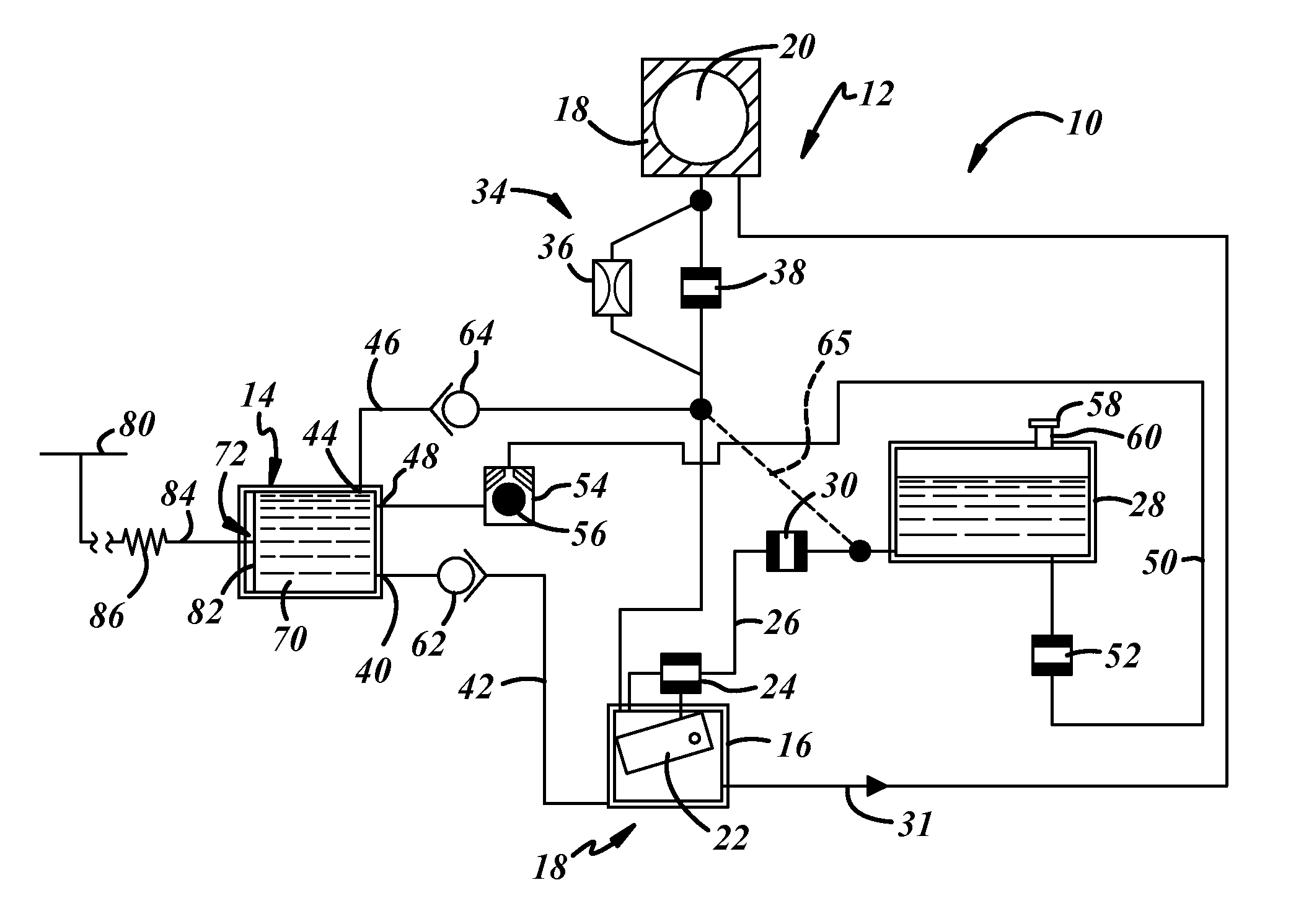
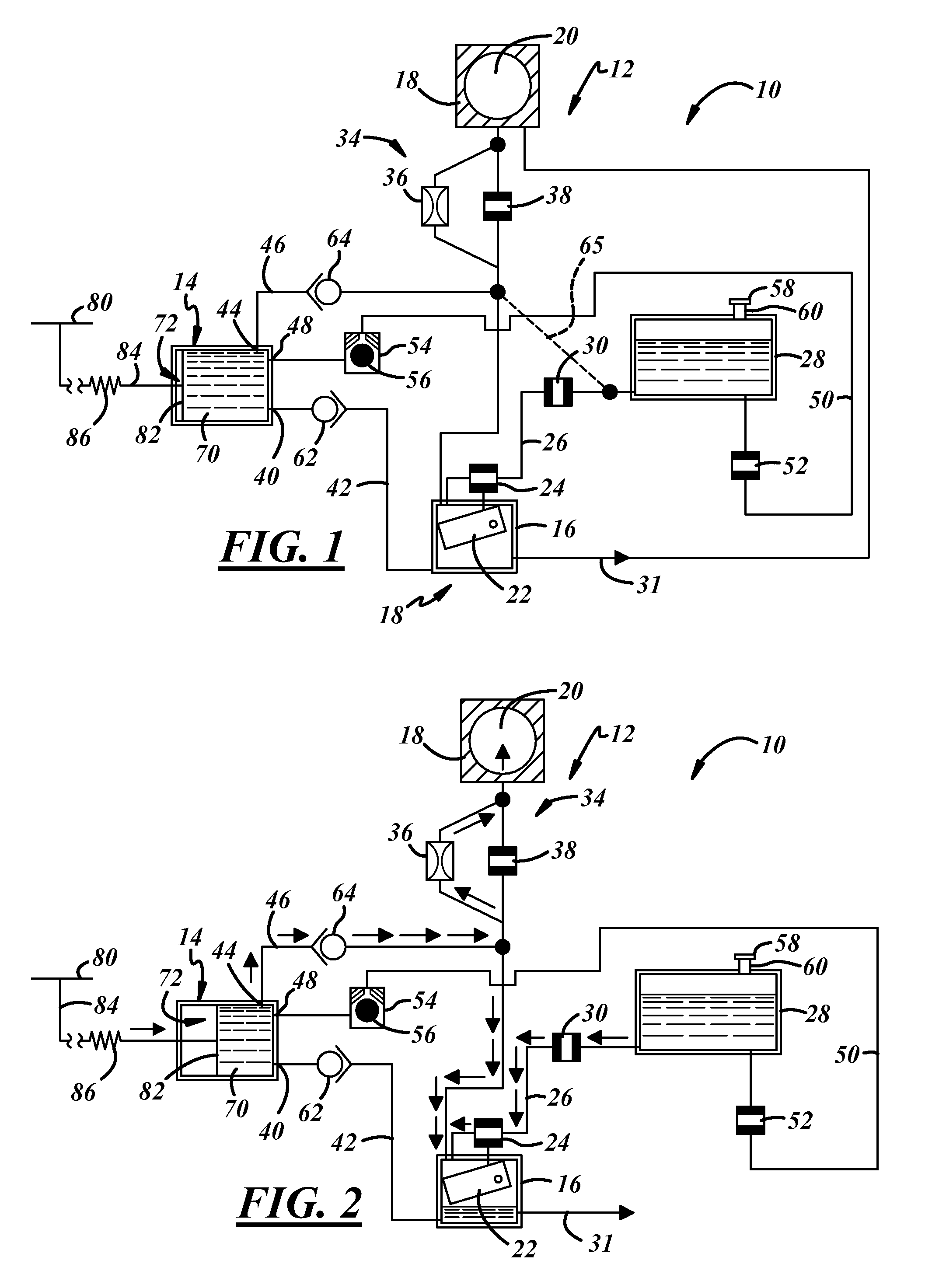
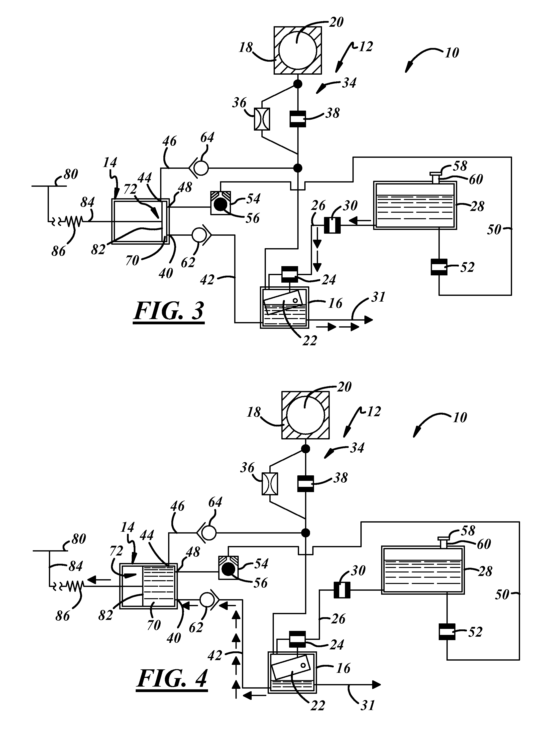
[0014]Referring in more detail to the drawings, FIGS. 1-5 illustrate a fuel system 10 including a charge forming device such as a float bowl carburetor 12 for supplying a combustible charge of fuel and air to support operation of an engine. The fuel system 10 preferably includes a drain unit 14 that may receive liquid fuel from a fuel source such as a float bowl 16 of the carburetor 12 when the engine is shut down, and refill the float bowl 16 when the engine is prepared for starting. Accordingly, the float bowl 16 may be drained when the engine is not running to limit hydrocarbon emissions therefrom, and also prevent fuel leakage or spillage as the engine or device is transported. Also, normal starting and operation of the engine may be facilitated with the return of fuel from the bowl drain unit 14 to the float bowl 16 prior to attempted starting of the engine. The system may be constructed generally as set forth in U.S. patent application Ser. No. 11 / 135,242, the disclosure of wh...


PUM


Abstract

A fuel system for a carburetor that supports operation of an engine includes a body with a bore, a fuel source communicated with the bore and from which fuel is supplied to the bore for delivery to the engine, a drain unit and a control. The drain unit is communicated with the fuel source to selectively receive fuel from the fuel source and has a fuel chamber and an actuator operable to vary the volume of the fuel chamber. The control is communicated with the actuator to permit fuel flow from the fuel source to the fuel chamber when the engine is shut down and to cause fuel to flow from the fuel chamber to the fuel source prior to starting the engine.

Description

REFERENCE TO COPENDING APPLICATION[0001]This application claims the benefit of U.S. Provisional Patent Application No. 60 / 887,469 filed on Jan. 31, 2007, which is incorporated herein by reference in its entirety.FIELD OF THE INVENTION[0002]The present invention relates generally to a carburetor and more particularly to a carburetor including a fuel source.BACKGROUND OF THE INVENTION[0003]Increasingly strict regulations promulgated by various governmental agencies including the Untied States Environmental Protection Agency and the California Air Resource Board place limits on the hydrocarbon emissions permitted from various small engine devices. One source of hydrocarbon emissions is the float bowl of float bowl type carburetors wherein a supply of fuel resides and is available for delivery from the carburetor to the operating engine. Upon shut down of the engine, the volume of fuel in the fuel bowl can evaporate. Upon evaporation of fuel, a float operated fill valve may permit addit...

Claims


Application Information

Patent Timeline
17 Aug 2010
Publication
US7775189B2
IPC
F02D41/06; F02N99/00
CPC
F02D35/0053; F02D41/042; F02D41/062; F02M37/0052; F02M37/0088
Inventors
BEJCEK, ANDREW E.; WOODY, JOHN C.