Brake booster stiffening plate

a technology of brake booster and stiffening plate, which is applied in the direction of cycle brakes, cycle equipment, vehicle components, etc., can solve the problems of inability to adjust the brake pads, inability to meet the needs of competition racing, and inability to meet the needs of braking system, etc., to achieve a shorter response time and promote less wind drag

Inactive Publication Date: 2010-08-17
FELT RACING
View PDF4 Cites 4 Cited by
  • Summary
  • Abstract
  • Description
  • Claims
  • Application Information

AI Technical Summary

Benefits of technology

[0011]This configuration provides for both a qu...

Problems solved by technology

Unfortunately, the cables and levers are externally exposed which may unacceptably increase drag for competition racing purposes.
Unfortunately, since only one lever is attached to one post, upon braking, each of the two levers pushes the pos...

Method used


Image

  • Brake booster stiffening plate
  • Brake booster stiffening plate
  • Brake booster stiffening plate

Examples


Embodiment Construction

[0018]The brake assembly 10 discussed herein is for a competition racing bicycle in which minute improvements of drag are considered significant over a long period of time and at peak performance levels. Additionally, execution of braking should be crisp and sensitive to provide the racer or cyclist predictable and reliable braking operation. Although the brake system 10 is most beneficial in relation to a competition racing bicycle, it is also contemplated that the brake system 10 may be employed in a recreational bicycle.

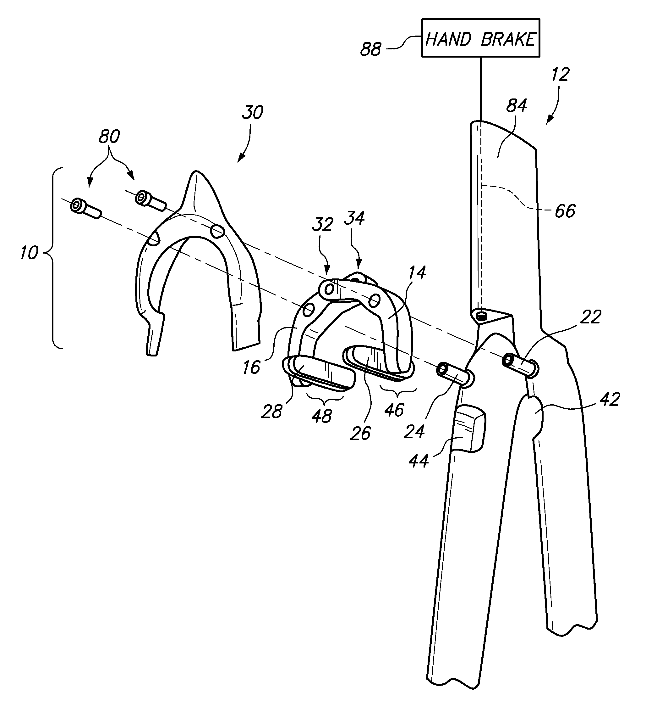
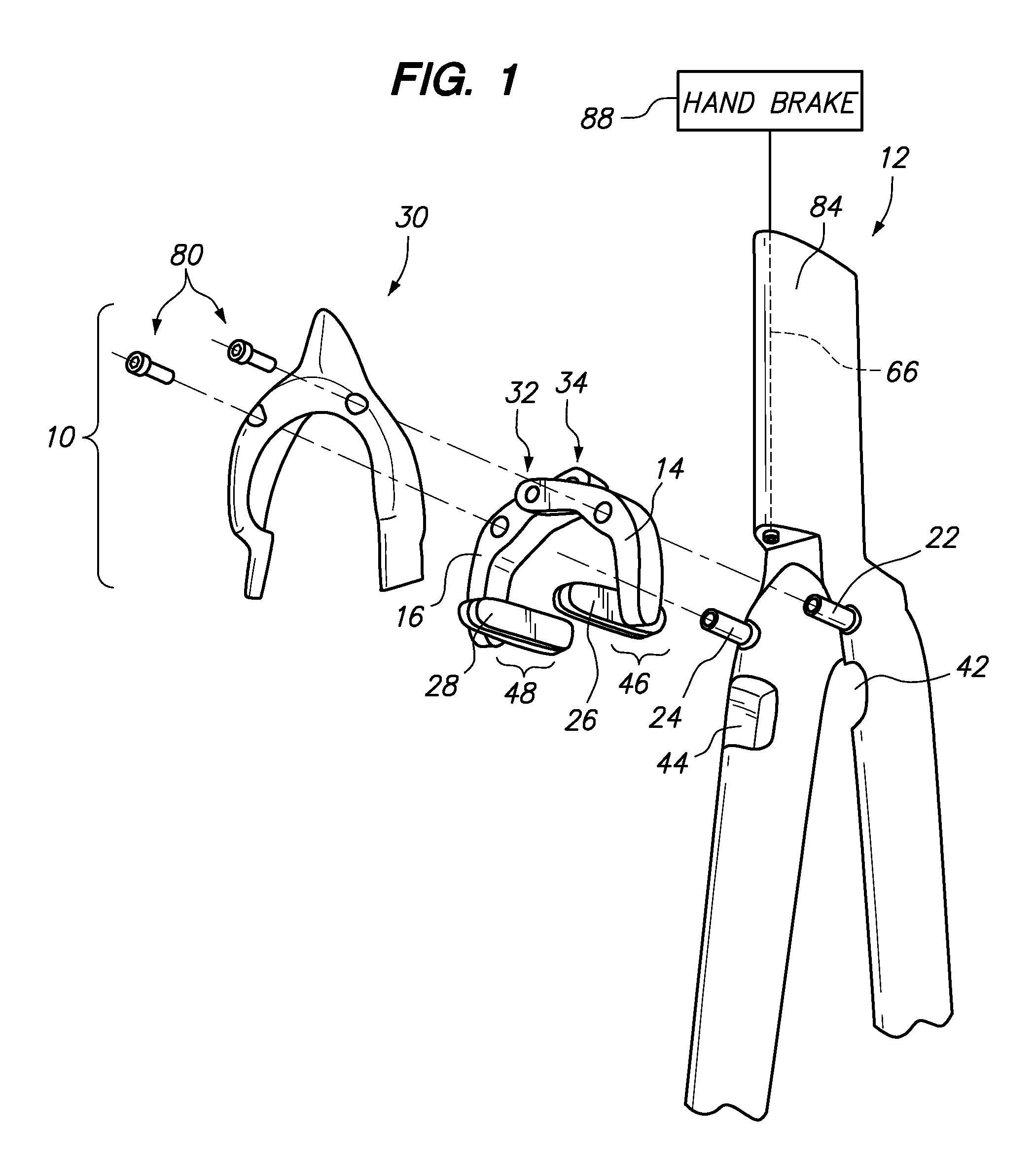
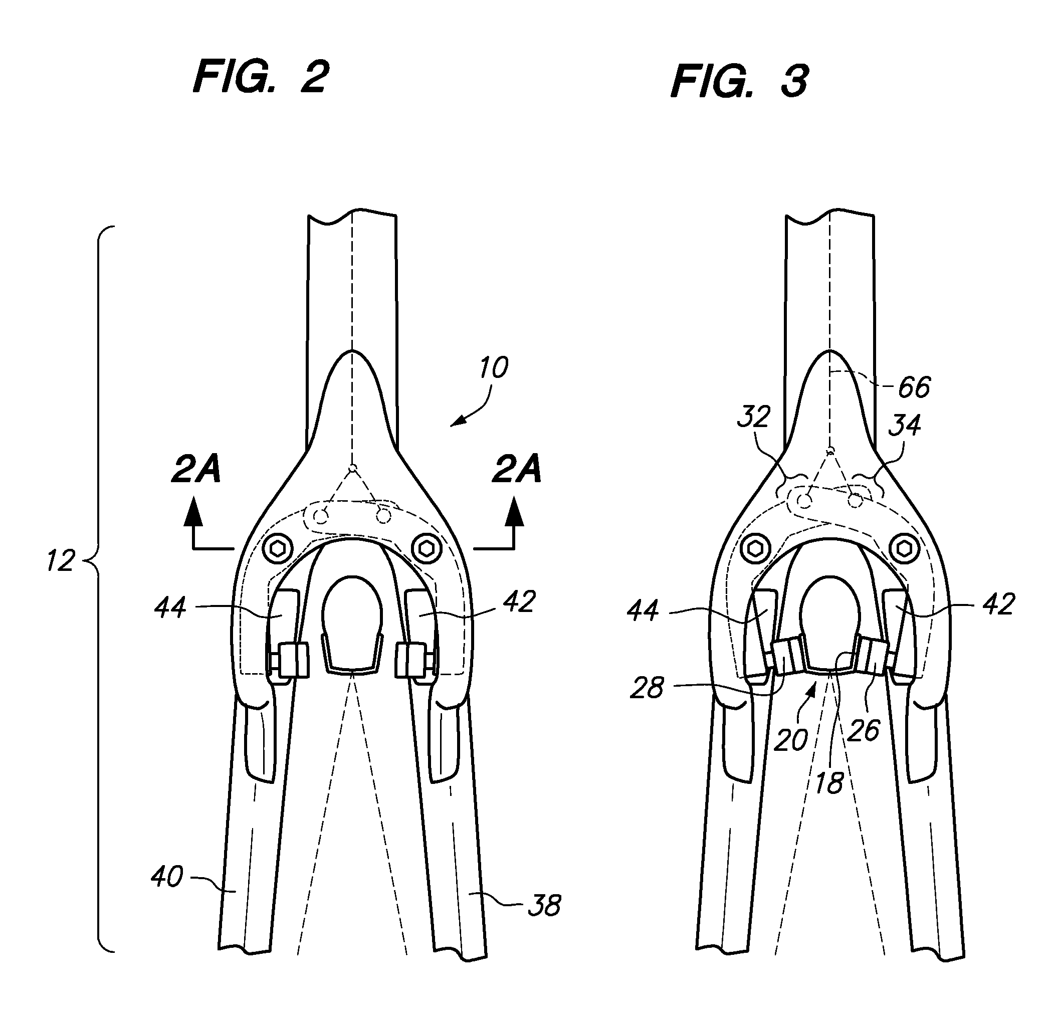
[0019]Referring now to FIG. 1, an exploded perspective view of a front brake assembly 10 is shown. The front brake assembly 10 is mounted to a front fork 12 of a bicycle. When the front brake assembly 10 is actuated to slow down the bicycle, left and right brake levers 14, 16 pivot and apply a braking force to a rim 18 (see FIG. 3) of a wheel 20. In order to apply the braking force to the rim 18, left and right brake pads 26, 28 apply inwardly directed forces to t...


PUM


Abstract

An aerodynamic brake booster stiffening plate is provided which attaches to pivot posts of a center pull brake system. The aerodynamic brake booster stiffening plate mitigates outward bending of the posts upon actuation of the brake to allow for faster brake response times. Additionally, a front surface of the aerodynamic stiffening plate may be aerodynamically shaped and blended with the fork or frame of the bicycle to encourage a laminar flow of air past the brake.

Description

CROSS-REFERENCE TO RELATED APPLICATIONS[0001]Not ApplicableSTATEMENT RE: FEDERALLY SPONSORED RESEARCH / DEVELOPMENT[0002]Not ApplicableBACKGROUND[0003]The present invention relates to a competition brake assembly having an aerodynamic configuration and a brake booster for promoting less wind drag and quicker brake response time.[0004]Numerous brake systems for bicycles exist. A common type of brake system for a road bicycle is a side pull brake system. The side pull brake system comprises left and right levers that pivot about a central post. First distal end portions of the levers have brake pads which are aligned to a rim of a bicycle wheel. Opposed second distal end portions of the levers are attached to a cable which may actuate the side pull brake system between a release position and a braking position. The pivot post, about which the levers rotate, is subjected to equal and opposing forces by the levers. As such, the post does not tend to bend to the left or right side of the b...

Claims


Application Information

Patent Timeline
IPC IPC(8): B62L1/00
CPCB60T1/06B62L1/16B62K19/38
Inventor FELT, JAMES MICHAELSOUCEK, JEFFREY ADELBERTLANE, TIMOTHY SAUL
Owner FELT RACING
Why Eureka
Try Eureka