Lift assembly, system, and method

a technology of lifting system and lifting rope, applied in the direction of curtain suspension device, door/window protective device, hoisting equipment, etc., can solve the problems of overcoming the overload limitation feature, exceeding the safe limit of suspension rope, and a significant cost of conventional counterweight system

Active Publication Date: 2010-08-17
ELECTRONIC THEATRE CONTROLS
View PDF58 Cites 21 Cited by
  • Summary
  • Abstract
  • Description
  • Claims
  • Application Information

AI Technical Summary

Problems solved by technology

However, conventional counterweight systems can represent a significant cost, with respect to both equipment required and time involved to install such equipment.
In such a rigging design, however, a number of additional bags can be added to the set of rope lines, and thereby exceed the safe limit of suspension ropes and defeat the overload-limiting feature.
When such winches are heavily loaded, the locking capacity of the ratchet lock, or other locking mechanism, can be overcome, resulting in the suspended load being dangerously dropped.
As a result, conventional lift systems can have less than effective safety mechanisms.
As a result, an undesired amount of horizontal stress can be placed on the overhead building supports to which the system and associated load are attached.

Method used


Image

  • Lift assembly, system, and method
  • Lift assembly, system, and method
  • Lift assembly, system, and method

Examples


Embodiment Construction

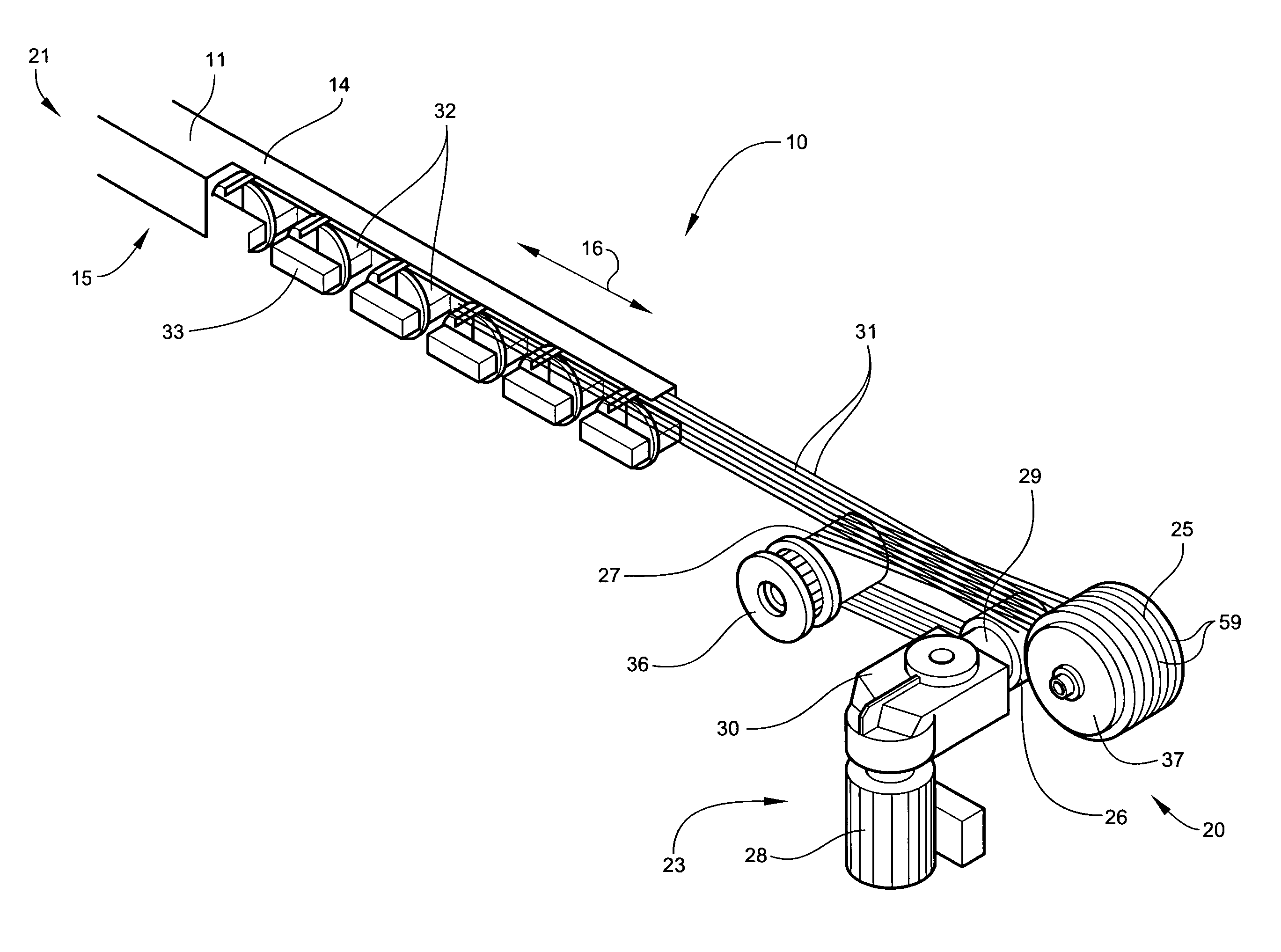
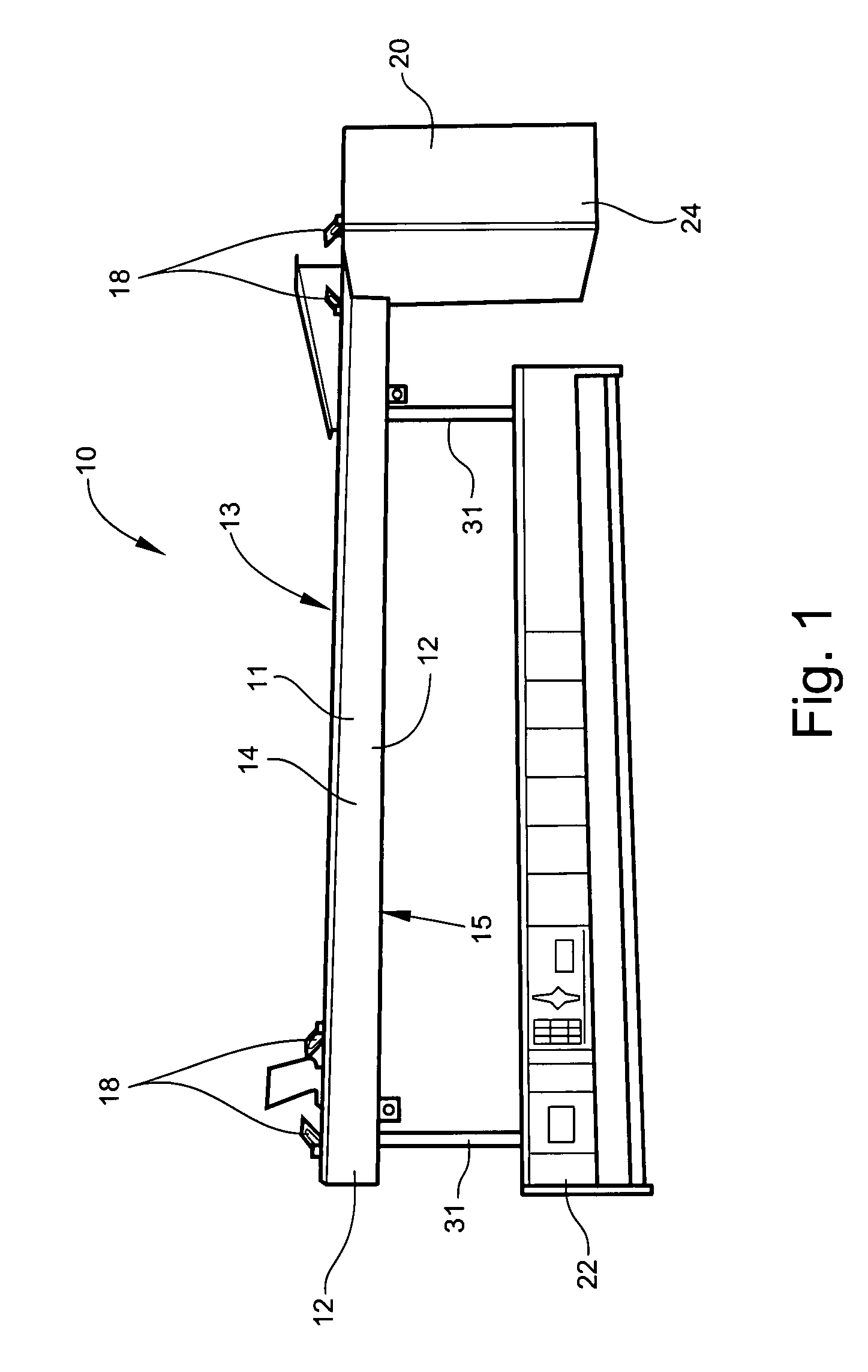
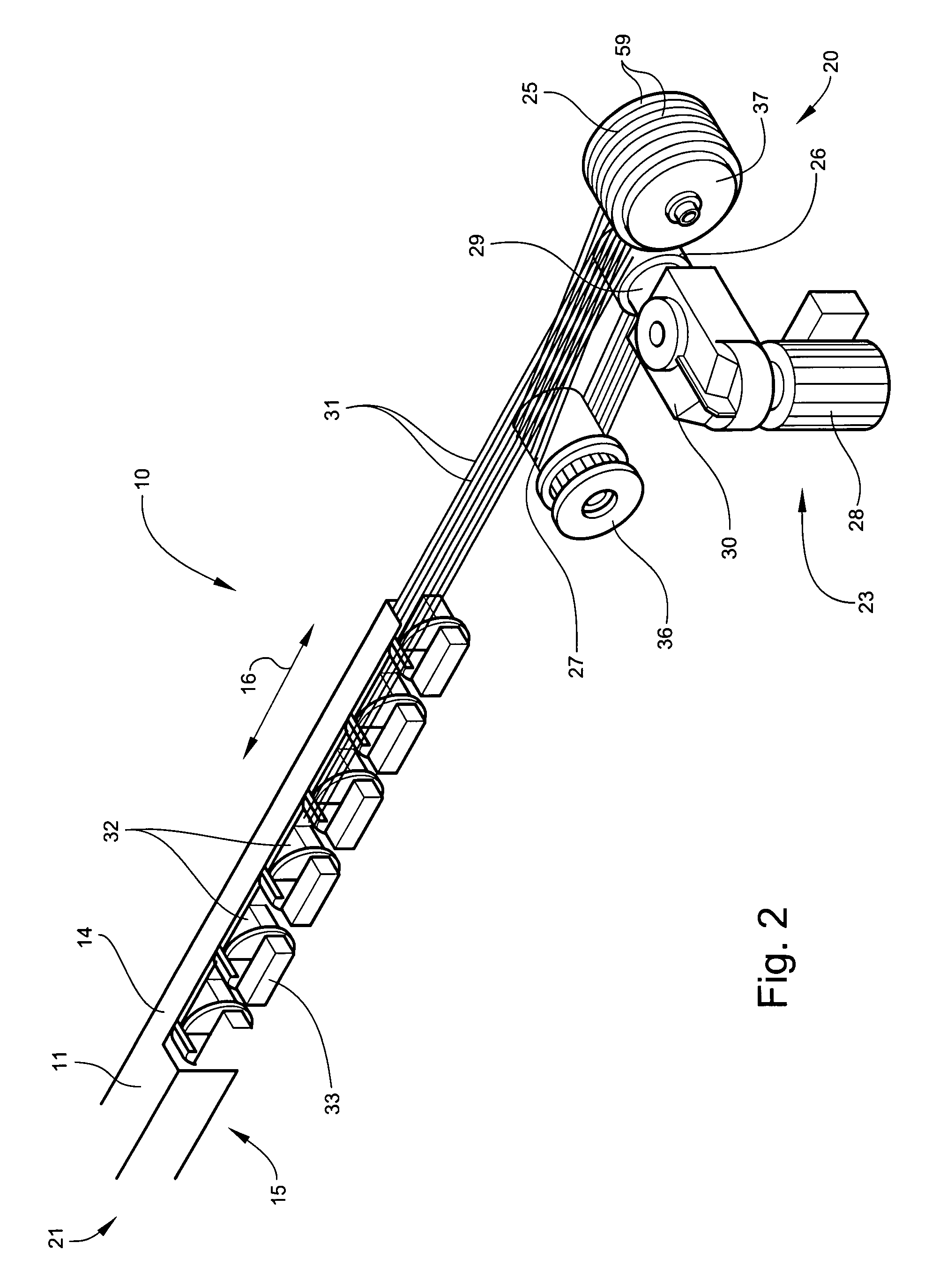
[0026]Some embodiments of the present invention can provide a lift assembly, system, and / or method. FIGS. 1-13 show various aspects of such embodiments. An illustrative embodiment of a lift assembly system 10 can include a coiling apparatus, or drum 25, a first traction drive 26 operably connected to a drive mechanism 23, a second traction drive 27, a tube 11 containing one or more pulleys, for example, a head block 39 and loft blocks 32, and one or more elongate members 31, such as cables. The cables 31 can be attached to the drum 25 and configured to travel in a generally horizontal path from the drum 25 around the second traction drive 27 to and around the first traction drive 26 to the head block 39 and the loft blocks 32 inside the tube 11. From the loft blocks 32, the cables 31 can travel in a generally vertical path, that is, upward and downward between the loft blocks 32 and a surface below. An article 22, or load, can be attached to the cables 31 such that when the cables 3...


PUM


Abstract

A lift assembly system and method can include a substantially rectangular tube, a motor operably connected to first and second traction drives and a rotatable drum and structurally connected to one end of the tube, a head block fixed to the opposite end of the tube, and a plurality of loft blocks positionable at an infinite number of locations within the tube. An elongate member attached on one end to the drum can be routed through a generally horizontal path from the drum to the first and second traction drives, the head block, and the loft blocks, and then through a generally vertical path from the loft block to an attached article. The elongate member can be wound about the drum to raise the article, and unwound from the drum to lower the article. The system can further include a load-side braking mechanism. The tube can include a compressible material adapted to absorb at least a portion of a horizontal load placed on the lift system.

Description

CROSS-REFERENCE TO RELATED APPLICATIONS[0001]This application claims benefit of U.S. Provisional Patent App. No. 60 / 873,389, filed Dec. 7, 2006, and U.S. Provisional Patent App. No. 60 / 796,362, filed on Apr. 28, 2006, each of which is incorporated by reference herein in its entirety.FIELD OF THE INVENTION[0002]The present invention relates to a lift assembly, system, and method. Embodiments of the present invention may be useful for raising and lowering a load in theatrical and staging environments.BACKGROUND OF THE INVENTION[0003]Performance venues such as theaters, arenas, concert halls, auditoriums, schools, clubs, convention centers, and television studios can employ battens or trusses to suspend, elevate, and / or lower lighting, scenery, draperies, and other equipment that can be moved relative to a stage or floor. Such battens can include pipe or joined pipe sections that form a desired length of the batten. Battens can be 50 feet or more in length. To support heavy loads or su...

Claims


Application Information

Patent Timeline
Patent Type & Authority Patents(United States)
IPC IPC(8): B66D1/36
CPCA63J1/028B66D1/741
Inventor HOFFEND, III, DONALD A.
Owner ELECTRONIC THEATRE CONTROLS
Why Eureka
Try Eureka