Interlocking method and its structure for wheel-rim cover

a technology of interlocking method and wheel rim cover, which is applied in the direction of wheel protection, vehicle components, transportation and packaging, etc., can solve the problems of occupying a lot of packaging space, the weight of the wheel rim also affects the acceleration capacity of the car, and the steel ring contributes to the high cost. , to achieve the effect of reducing the stocking spa

Inactive Publication Date: 2010-08-17
CHEN CHEN CHUN
View PDF17 Cites 42 Cited by
  • Summary
  • Abstract
  • Description
  • Claims
  • Application Information

AI Technical Summary

Benefits of technology

[0009]In view of the above defects, the present invention provides an interlocking method and its structure for a wheel-rim cover in which interlocking blocks are used to insert and combine the wheel-rim cover body on the front side of the wheel-rim body so as to ensure that the wheel-rim cover body will not detach from the wheel-rim body. In addition, the engaging seats do not affect the stacking height of the wheel-rim cover bodies, such that the stocking space can be reduced.

Problems solved by technology

Aside from the closely linked relationship between the size and the aspect ratio of the tire, the weight of the wheel-rim also affects acceleration capacity of car.
However, the above interlocking structure for a wheel-rim cover has the following defects in practical application.3. The above interlocking structure for a wheel-rim cover uses a steel ring to support the interlocking body of the wheel-rim cover so that the interlocking body of the wheel-rim cover can be inserted and engaged with the ring edge of the car wheel-rim.
However, the steel ring contributes to the high cost.4. The above interlocking structure for a wheel-rim cover uses the interlocking body to insert and engage the wheel-rim cover with the wheel-rim of a car.
However, the interlocking body can not be folded so that wheel-rim cover takes a lot of space in packaging.
Accordingly, not only the added delivery cost is increased but also business competitiveness of the manufacturer becomes weaker.

Method used


Image

  • Interlocking method and its structure for wheel-rim cover
  • Interlocking method and its structure for wheel-rim cover
  • Interlocking method and its structure for wheel-rim cover

Examples


Embodiment Construction

[0026]The technical contents of the present invention will become more apparent from the detailed description of the preferred embodiments in conjunction with the accompanying drawings.

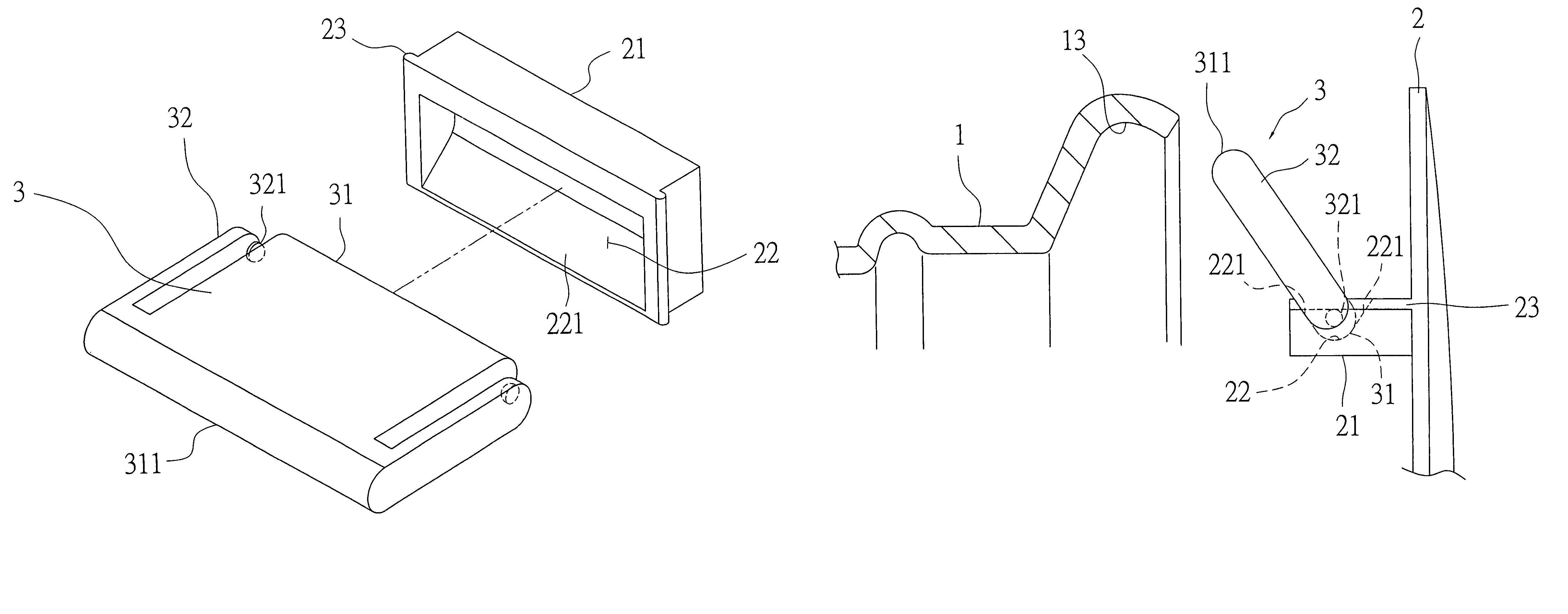
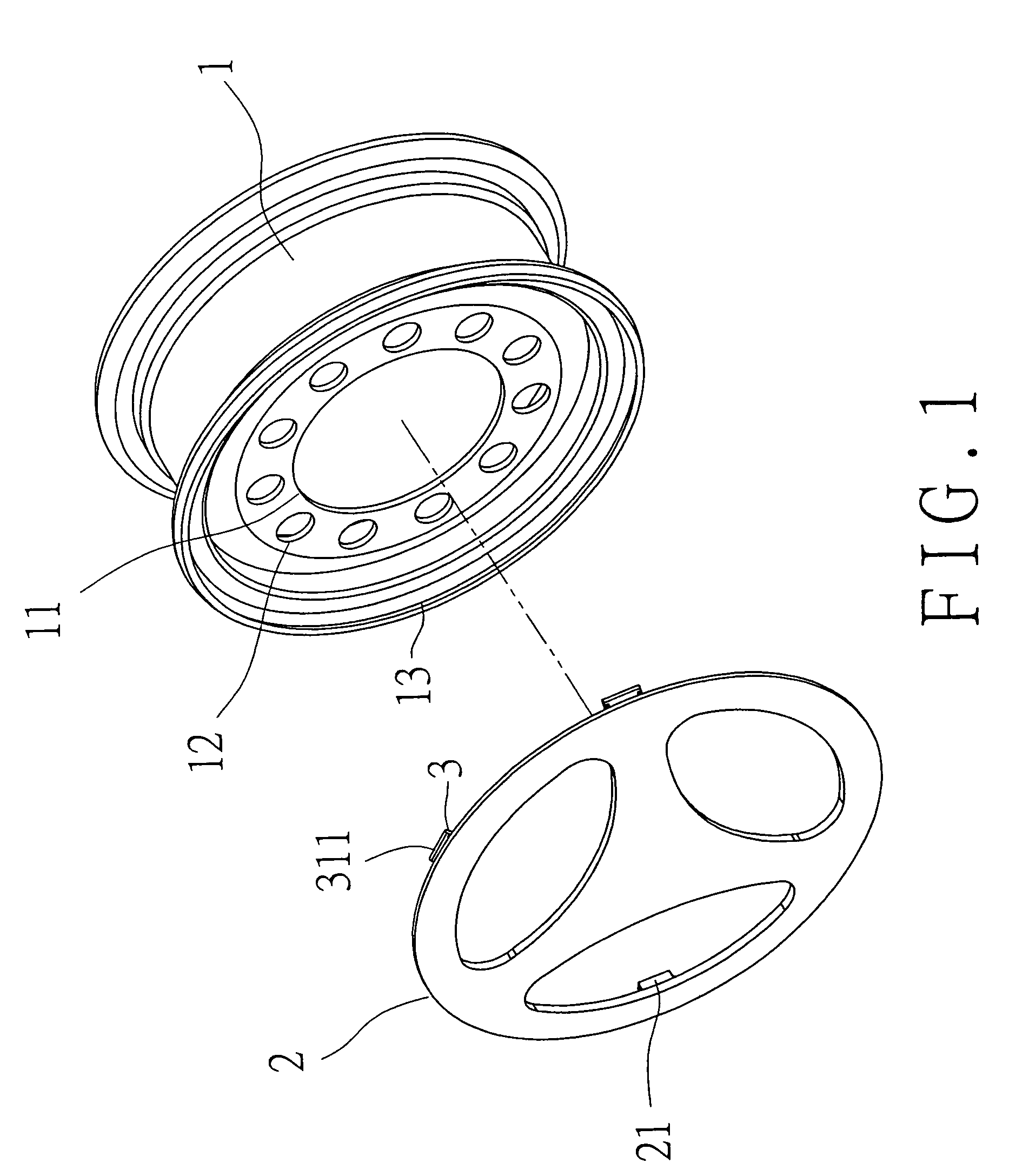
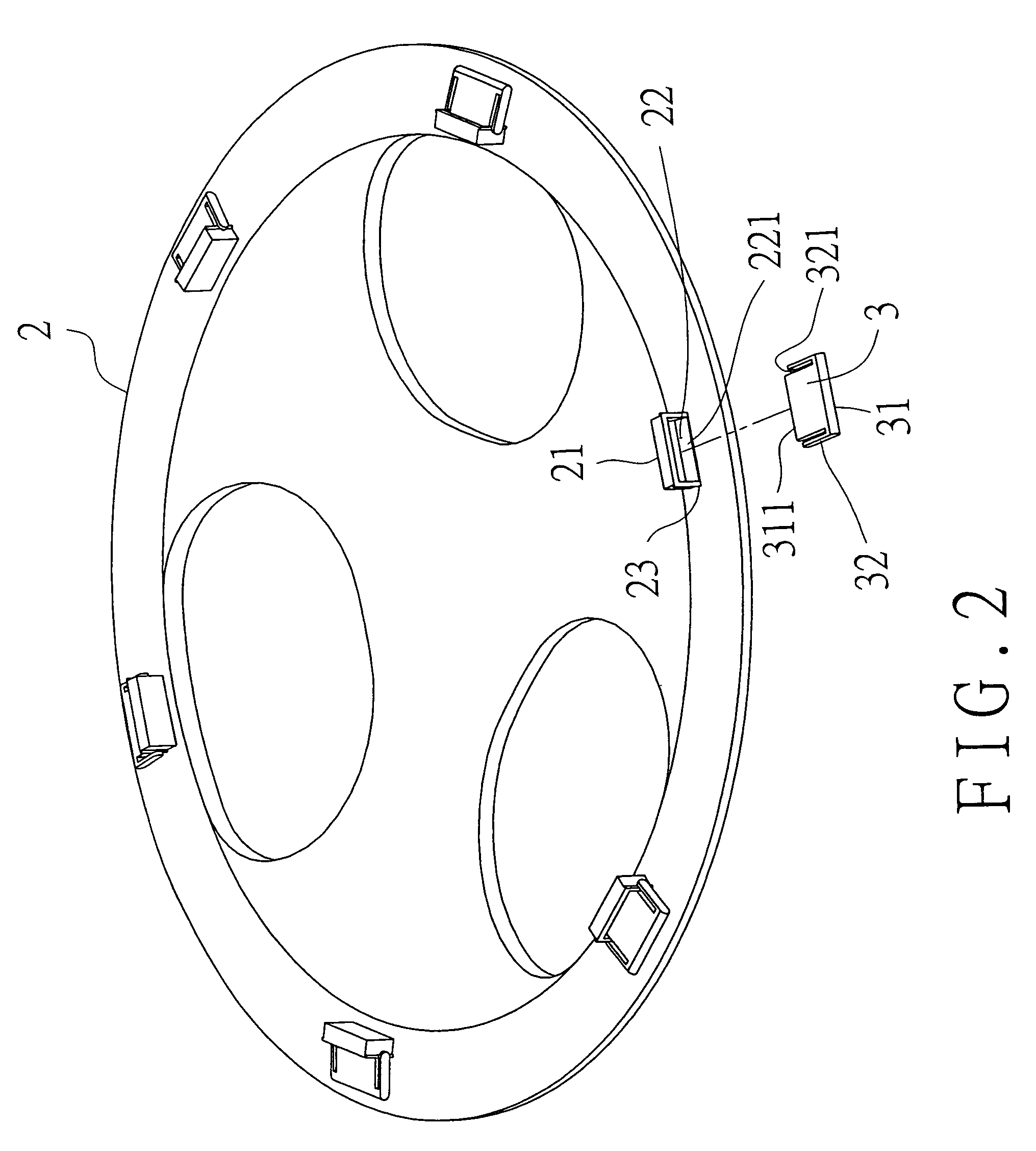
[0027]Firstly referring to FIG. 1 showing a schematic view of the first embodiment of the interlocking method and its structure for a wheel-rim cover of the present invention, a wheel-rim body (1), a wheel-rim cover body (2) and a plurality of interlocking blocks (3) are included therein.

[0028]The wheel-rim body (1) is made of a metal material by casting or forging. The inner peripheral walls on the front and rear sides of the wheel-rim body (1) are respectively coupled with a hub (11) in which a plurality of holes (12) are arranged in ring shape. Both the front and rear outer edges of the wheel-rim body (1) are bent inward respectively to form an engaging groove (13) for engagement with the interlocking blocks (3), so that the wheel-rim cover body (2) can be fixed on the front side of the wheel-rim b...


PUM


Abstract

An interlocking method and its structure for wheel-rim cover is provided and includes a plurality of engaging seats integrally formed along the peripheral edge of the rear side of a wheel-rim cover body. Each engaging seat has an interlocking block pivotally coupled thereto. An inner edge of the interlocking block forms the pivotal axis thereof and is displaceably disposed on an inclined surface of an engaging slot formed in the engaging seat. The outer edge of the interlocking block is displaceably disposed in an engaging groove of the wheel-rim body. By that arrangement, displacement of the wheel-rim cover body toward the hub of the wheel-rim body results in a displacement of the interlocking block to provide respective frictional engagement of the inner and outer ends of the interlocking block with the inclined surface of the engaging slot and the surface of the engaging groove.

Description

BACKGROUND OF THE INVENTION[0001]1. Field of the Invention[0002]The present invention relates to an interlocking method and its structure for a wheel-rim cover, particularly to an interlocking method and its structure for a wheel-rim cover in which interlocking blocks are used to insert and combine the wheel-rim cover body on the front side of the wheel-rim body, without affecting the stacking height of the wheel-rim cover bodies, such that the stocking space can be reduced.[0003]2. Brief Description of the Prior Art[0004]Wheel-rims are closely linked with the performance and manipulation capacity of the car, though not to be regarded as the main structure of the car body. Aside from the closely linked relationship between the size and the aspect ratio of the tire, the weight of the wheel-rim also affects acceleration capacity of car. Moreover, the wheel-rim plays an important role in the appearance and the whole design of a car. Accompanying with the progress in material science, t...

Claims


Application Information

Patent Timeline
Patent Type & Authority Patents(United States)
IPC IPC(8): B60B7/10
CPCB60B7/02B60B7/10
Inventor CHEN, CHEN-CHUN
Owner CHEN CHEN CHUN
Why Eureka
Try Eureka