Ink jet device with a ventilation conduit

a technology of ventilation conduit and ink jet, which is applied in the direction of measurement devices, printing, instruments, etc., can solve the problems that the conduit may also have a non-return valve, and achieve the effects of reliable ventilation, enhanced measuring accuracy, and greater freedom in the design of the print head

Inactive Publication Date: 2010-08-17
OCE TECH
View PDF4 Cites 0 Cited by
  • Summary
  • Abstract
  • Description
  • Claims
  • Application Information

AI Technical Summary

Benefits of technology

[0004]It is an object of the present invention to provide an ink jet device with an ink reservoir for melted hot melt ink which is provided with a more reliable ventilation system.
[0005]According to the present invention, this object is achieved by an ink jet device of the kind mentioned above wherein a channel runs upwards through a heated area. The channel is heated by the heated area to a temperature that is above a melting point of the ink. Thereby, any ink entering the ventilation conduit from the ink reservoir will be maintained in the melted state and will flow downwards back into the ink reservoir. Thus, clogging of the ventilation conduit is prevented. The smaller the diameter of the channel, the higher the ink might rise within the channel. Therefore, the invention is especially advantageous when the maximum diameter of the channel is smaller than half the length of the channel, and even more advantageous when the maximum diameter of the channel is smaller than one quarter of the length of the channel.
[0010]According to a further development of the present invention, the ink jet device comprises an ink melting unit for supplying melted ink to the ink reservoir, said ink melting unit being arranged to enable melted ink to flow into the ink reservoir from above, said channel of the ventilation conduit being in thermal contact with the ink melting unit. For example, the ventilation conduit runs along or through the ink melting unit and is heated by the ink melting unit. Thus, the heat supplied by the ink melting unit is utilized for heating the channel of the ventilation conduit. This is advantageous, because the heated area through which the channel runs and the ink melting unit both have to be maintained at a temperature where the ink melts. Moreover, during a sleep mode of a printer, for example, it will be less probable that ink enters into the ventilation conduit, so that the ventilation conduit may be allowed to cool down together with the ink melt unit.
[0012]In another embodiment, the ventilation conduit is not guided through the melting unit but is separated therefrom such that no thermal contact exist between the ventilation conduit and the melting unit. In the latter case a separate heater may be provided to heat at least the lower part of the ventilation conduit which communicates with the ink reservoir. The lower part of the ventilation conduit is the part which may be exposed to intrusion of the melted ink from the ink reservoir. This intrusion may originate from uncontrolled movement of the melted ink and / or from overfilling of the ink reservoir and / or from suction, and / or from capillary forces. Separating the ventilation conduit from the melting unit creates a greater freedom in designing the print head.
[0013]In a preferred embodiment, a wall of the ink reservoir comprises an ink filter, the ink filter and the ink melting unit being arranged to enable melted ink to flow from the melting unit through the ink filter into the ink reservoir, the ventilation opening being arranged separately from the ink filter. By arranging the ventilation opening separately from the ink filter, the ink does not have to flow through the ventilation opening into the ink reservoir. Thus, a more reliable ventilation is achieved.
[0014]Preferably, a pressure sensor is arranged at the channel. The pressure sensor senses a pressure within the channel and can be utilized to monitor the negative pressure that is applied to the space of the ink reservoir. By arranging the pressure sensor at the channel, the sensor is at a position that is normally not filled with ink and, moreover, will be heated at least approximately to a determined temperature, thus enhancing the measuring accuracy.

Problems solved by technology

However, the ventilation conduit may also have a non-return valve that closes in the case of a high enough pressure within the ink reservoir.

Method used


Image

  • Ink jet device with a ventilation conduit
  • Ink jet device with a ventilation conduit

Examples


Embodiment Construction

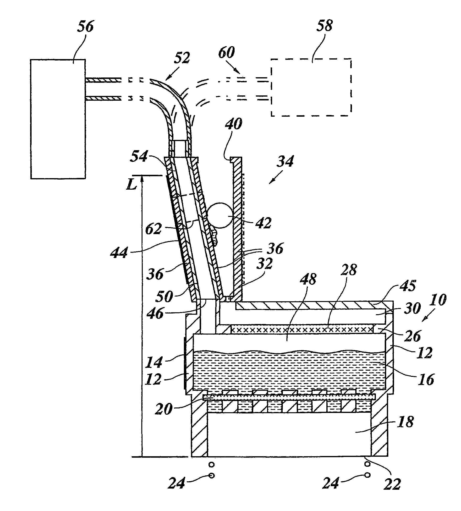
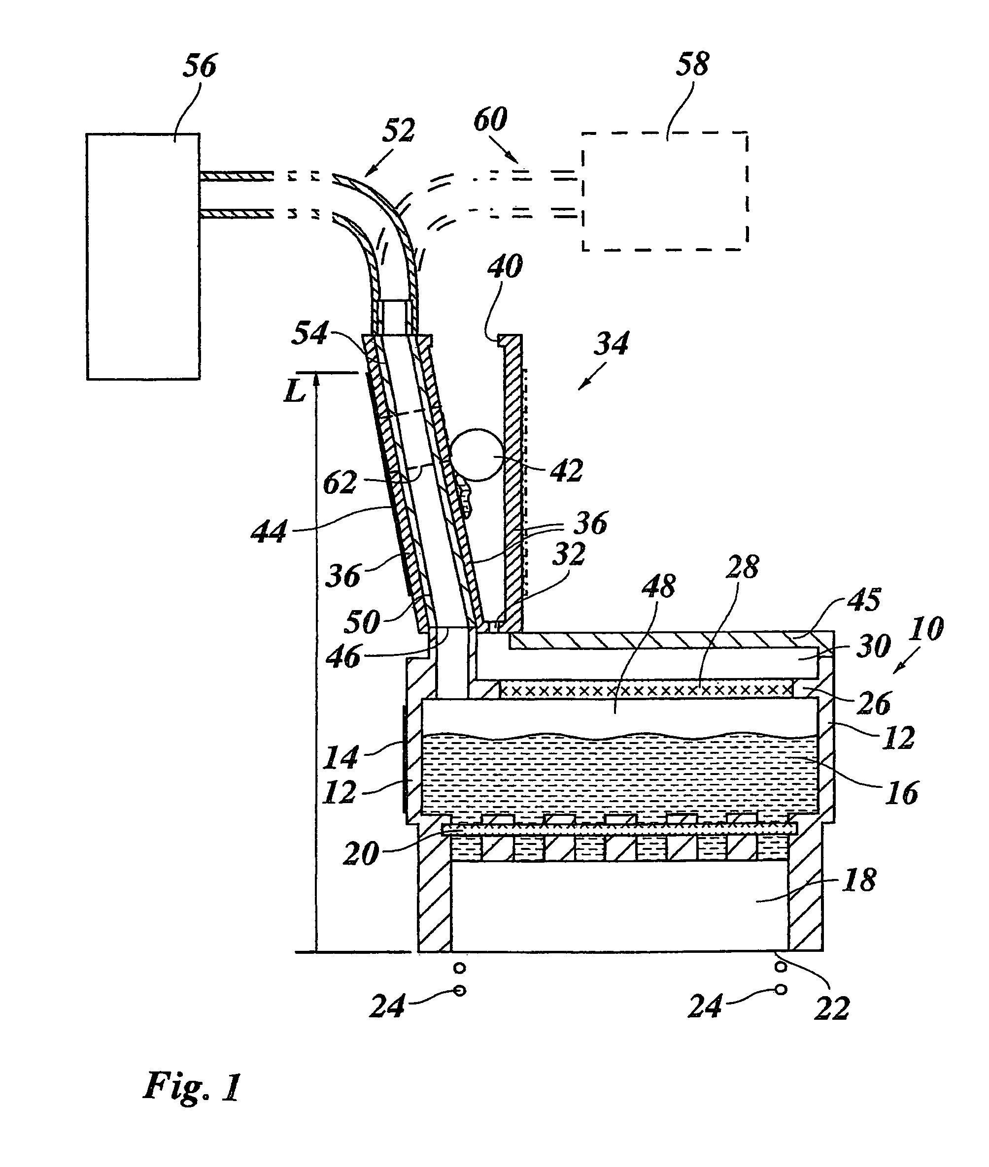
[0017]The ink jet device comprises an ink reservoir 10 having walls 12 made of thermally conductive material. As is generally known in the art, an electric heater 14 is in contact with or integrated in the walls 12 of the ink reservoir so that hot melt ink 16 contained in the ink reservoir is maintained at a temperature of, for example, 120° C. and in any case at a temperature above its melting point, so that the ink is kept in a liquid state and is ready to be supplied to an ink jet printhead 18 which is arranged below the ink reservoir and which is in fluid connection with the ink reservoir 10 via a filter 20. The ink jet printhead 18 comprises printing nozzles 22, as generally known in the art. Some ink jets 24 are indicated as examples. As is also generally known in the art, the ink reservoir 10 and the printhead 18 may be mounted on a reciprocating carriage of a printer, so that the ink reservoir 10 is moved back and forth in the direction of the line of sight of the figure whe...


PUM


Abstract

An ink jet device utilizing hot melt ink, said device including an ink reservoir, a heater arranged to heat ink contained in the ink reservoir, and a ventilation conduit which is connected to a ventilation opening in a top wall of the ink reservoir, said ventilation conduit containing a channel running upwards through a heated area. The ink jet device includes an ink melting unit for supplying melted ink to the ink reservoir, said ink melting unit being arranged to enable melted ink to flow into the ink reservoir from above, said channel of the ventilation conduit being in thermal contact with the ink melting unit.

Description

[0001]This application claims priority under 35 U.S.C. §119(a) on Patent Application No. 05109633.7 filed in Europe on Oct. 17, 2005, the entire contents of which is hereby incorporated by reference.BACKGROUND OF THE INVENTION[0002]The present invention relates to an ink jet device comprising an ink reservoir for hot melt ink, a heater arranged to heat ink contained in the ink reservoir, and a ventilation conduit which is connected at a lower end thereof to a ventilation opening in a top wall of the ink reservoir, said ventilation conduit comprising a channel, the maximum diameter of which is smaller than the length of the channel. For example, the channel consists of a tube.[0003]Ink jet printers operating with hot melt ink, i.e., with ink that is solid at room temperature, comprise an ink reservoir which can be heated in order to maintain the ink in the liquid state in which it can be supplied to the printhead. To prevent ink from leaking through a printing nozzle of the printhead...

Claims


Application Information

Patent Timeline
Patent Type & Authority Patents(United States)
IPC IPC(8): B41J2/175
CPCB41J2/17593
Inventor JOPPEN, SANDOR H. G.HOLLANDS, PETER J.
Owner OCE TECH
Why Eureka
Try Eureka